52
PARAMETER-SETTING MANUAL
VARMECA 30
Variable speed motors and geared motors
SWITCHING TO PROTECTIVE MODE – DIAGNOSTICS
LEROY-SOMER
3847 en - 2013.06 / i
• The user must not attempt to repair the drive,
or perform any diagnostics other than those listed
in this section. If the drive malfunctions, it should be
returned to LEROY-SOMER via your usual contact.
The LCD KEYPAD or PAD VMA options give a certain amount
of information which simplifies the diagnostic process.
This information is broken down into 2 categories:
– Information concerning operation
– Fault tripping
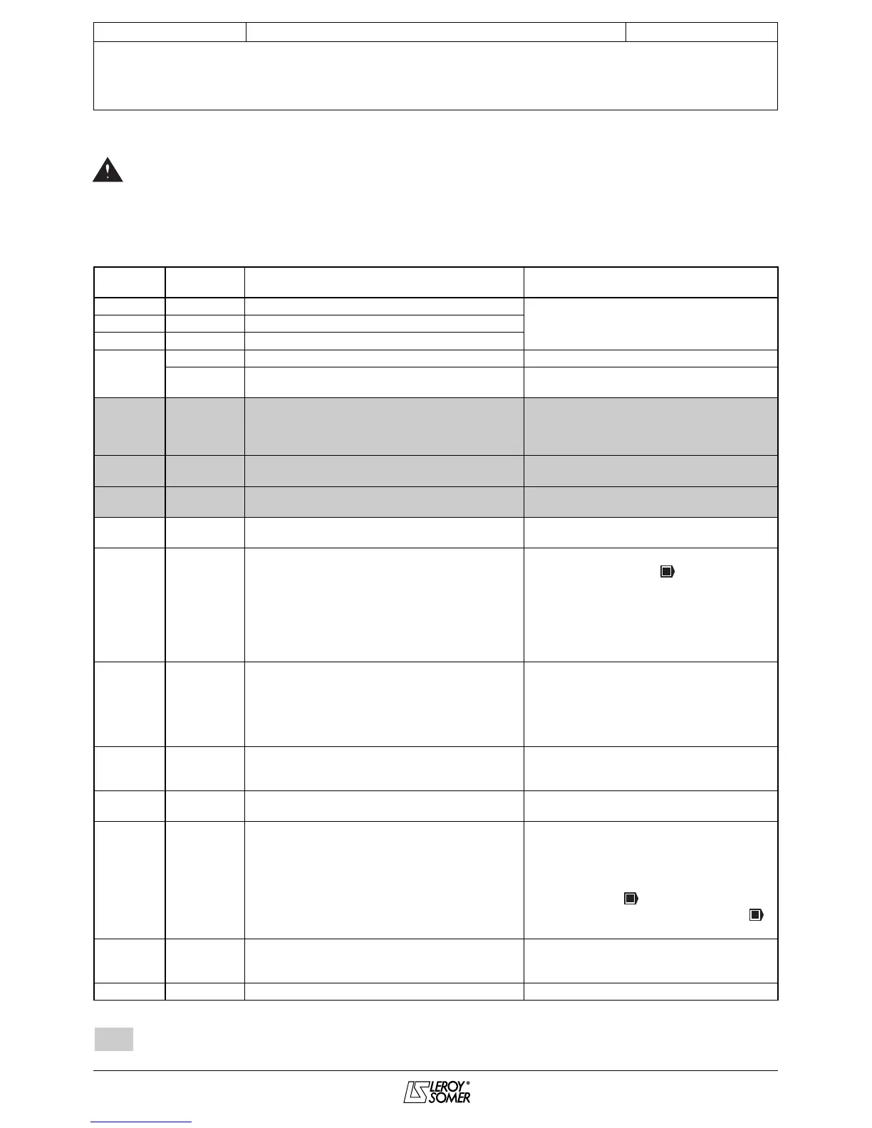
If the drive switches to protection mode, the drive output
bridge is inactive, and the drive no longer controls the motor.
The display indicates "triP" and the fault code alternately.
All the faults indicated by the display unit are listed in the
following table in alphabetical order.
: Faults specific to the VMA 33/34
PAD
VMA30
LCD
KEYPAD
Cause Solution
cL1 4 mA ADI1 Loss of the current reference on analogue input ADI1
• Check the connections of analogue input
ADI1, ADI2 or ADI03
• Check that the reference is > 3 mA
cL2 4 mA ADI2 Loss of the current reference on analogue input ADI2
cL3 4 mA ADIO3 Loss of the current reference on analogue input ADIO3
EEF
The drive rating does not correspond to XPress Key
EEPROM EEPROM fault
• Perform a return to factory settings procedure
(see 65)
EnC1
Chann. U
encod.
Loss of channel U
• Check the connection and supply voltage of
the encoder
• Check the speed feedback
• Replace the encoder
EnC2
Chann. V
encod.
Loss of channel V • Check the encoder voltage and connections
EnC3
Chann. W
encod.
Loss of channel W • Check the encoder voltage and connections
Fbus Bus loss Disconnection of the fieldbus during operation
• Check the connections
• Check the fixing of the fieldbus option
It.AC
I
2
t motor Motor overload I
2
t
• Check that the motor is not overloaded
• Adjust the rated speed ( )
• Check that the motor rated current is set
correctly (06)
• Speed feedback: Check the coupling, and
check that the signal is not subject to
interference
• Check the number of motor poles in 62
It.br Brake resist.
Braking resistor overload I
2
t
• Read the battery value in 10.39
• Increase the resistor ohmic value
• Check that 10.30 and 10.31 are set correctly
(braking cycle too long)
• Check the resistor wiring
• Check the integrated transistor
Oht1 IGBT temp. IGBT overheating (sensor)
• Reduce the motor load, the cycle, the
switching frequency, and the acceleration and
deceleration ramps
Oht2 RF int. temp. Internal resistor overheating (sensor)
• Reduce the switching frequency
• Reduce the cycle and the motor load
OI.AC
Drive output
curr.
Overcurrent at drive output
or instability and vibration
*
• Check the motor insulation and connection
• Increase the acceleration and deceleration
ramps
• Perform another calibration
• Check the wiring, coupling and the speed
feedback signals ( )
• Reduce the speed loop gains 29 and 30 ( )
• Reduce the current loop gains 31 and 32
OI.br
Brake IGBT
curr.
Braking IGBT overcurrent
• Check the resistor insulation
• Correct the short-circuit at the resistor output
• Set a higher resistor ohmic value
OLd1 +24 V Ovrld. Overload on + 24V source or digital output • Check the total current consumption
3 - SWITCHING TO PROTECTIVE MODE – DIAGNOSTICS
 Loading...