TO DRAIN UNIT FOR PROLONGED SHUT-DOWN
(Where drainage is necessary)
1. Turn off steam supply and water supply.
2. Open a vent line in high point of system piping.
3. Remove relief valve to drain water from control valve.
4. Open drain connections in steam and condensate lines.
5. Be sure all water is drained from hot water control valve
and system if there is any danger of freezing.
6. When restarting system, tighten all connections and
close all vents. Follow instructions shown in Section II -
Start-up Procedure to put Heater back in operation.
SECTION III
MAINTENANCE OF SYSTEM COMPONENTS
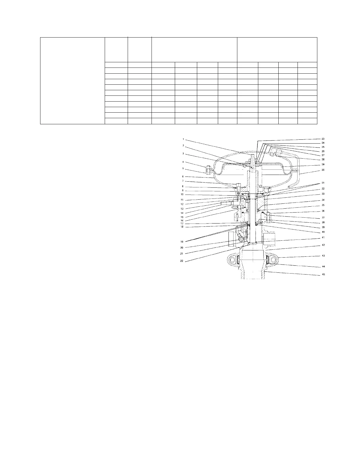
Hot Water Control Valves Dismantling
1. Close all steam and water inlet and outlet stop valves.
Disconnect tubing from valve body and upper
diaphragm case.
2. Disconnect Victaulic coupling (43) and remove gasket
(44). Remove reducing coupling (45) and remove tubing
(30).
3. Loosen and remove casing bolts (5) and nuts (4). Lift off
upper diaphragm case (27).
4. Remove retaining ring (15) from temperature adjustor
(14) followed by lock nut (13) and cover plate (16).
5. Take out retaining ring (12) from adjusting sleeve (33)
and take out temperature adjustor (14) and key cylinder
(10).
6. Hold upper stem (1) fast by placing an open end
wrench on the upper stem flats and remove the jam nut
(23) with another wrench.
7. Take out the shouldered washer (25), O-ring (24),
diaphragm (26), diaphragm plate (29), control valve
spring (3), and the spring guide washer (2) from the
lower diaphragm case (6).
CAUTION: Do not allow valve plug assembly to fall from lower
end of the valve body.
8. Take valve plug assembly from lower opening of valve
body (42).
9. Remove socket head cap screws (7) and take off lower
diaphragm case (6). Take out O-ring (8) from top of yoke
(36).
10. Disconnect Victaulic couplings from valve body (42) and
remove gaskets.
Page 3
Figure 1
E-300L, E-320LDW,
E-600L, E-620LDW,
E-1500L, E-4500L
CAPACITY
AND
ADJUSTMENT
TABLE
(Capacity in GPM)
Numbers in brackets are
approximate Gain Adjustor
settings in degrees.
* Maximum water temperature
setting for E-1500L and E-300L
is 150º
** Steam pressure is measured
at the Heat Exchanger inlet.
INLET E-1500LM E-300L, E-320LDW E-4500L, E-600L, E-620LDW
WATER SET
TEMP POINT **STEAM PRESSURE PSIG **STEAM PRESSURE PSIG
ºF ºF
2 5 10 15 2 5 10 15
120 27(25º) 20(24º) 30(23º) 30(22º) 54(15º) 60(14º) 60(13º) 60(12º)
140 20(30º) 22(30º) 24(30º) 27(30º) 46(36º) 54(25º) 58(25º) 60(20º)
40 150 17(30º) 19(30º) 21(30º) 23(30º) 40(30º) 49(30º) 53(27º) 54(25º)
160 * * * * 34(30º) 41(30º) 44(30º) 46(30º)
180 * * * * 21(30º) 23(30º) 25(30º) 28(30º)
12 30(22º) 30(21º) 30(20º) 30(19º) 60(12º) 60(11º) 60(10º) 60(9º)
140 23(25º) 25(24º) 27(23º) 30(22º) 57(15º) 59(14º) 60(13º) 60(12º)
60 150 20(28º) 22(27º) 24(27º) 27(26º) 49(23º) 54(21º) 57(18º) 60(16º)
160 * * * * 42(30º) 49(28º) 51(25º) 56(20º)
160 * * * * 29(30º) 33(30º) 39(30º) 44(30º)


 To Next Page