Page 4
11. Take out cap screws (39) and remove valve body (42).
12. Push temperature adjusting sleeve (33) out of yoke (36).
13. Valve plug assembly should not be disassembled
unless parts replacement is necessary due to wear or
damage. For disassembly, see instructions covering
assembly of valve plug and reverse instruction
procedure.
14. All parts should be cleaned with an approved solvent.
Wipe off with a clean cloth. Do Not Use Abrasives of
any kind. Care should be taken in handling parts so as
not to damage critical surfaces. Replace any badly
worn or damaged surfaces.
NOTE: If a complete dismantling of control valve is necessary,
it is recommended that valve be removed from Heater and
work performed on a work bench.
ACTUATOR ASSEMBLY
IMPORTANT: Lubricate all O-rings with Silicon Grease.
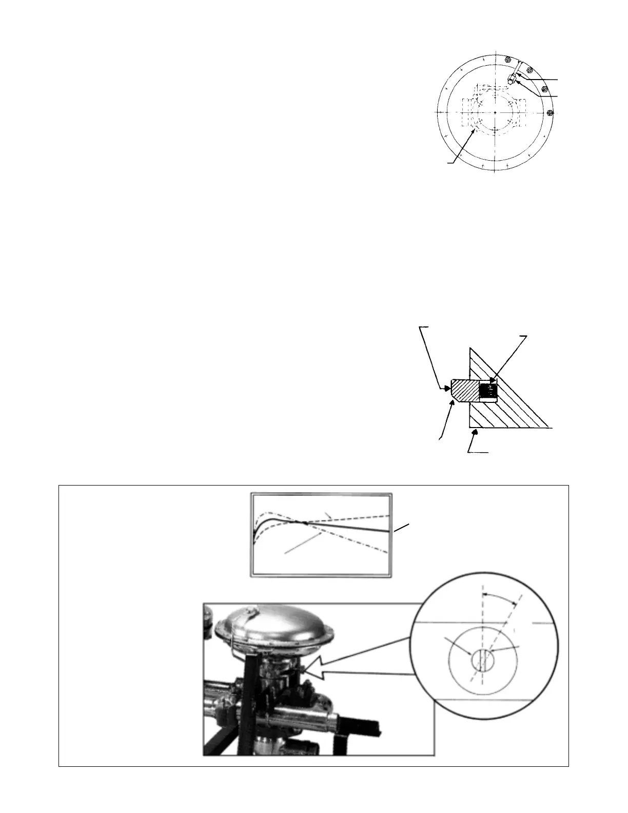
1. Place O-ring (8) in the top of yoke (36). Position and
attach lower diaphragm case (6) to the yoke. (See Fig.
3) Fasten case to the yoke with cap screws 97)
sequentially from each other until tight.
2. Install O-ring (37) in temperature adjusting sleeve (33)
grooves. Insert guide energizer (35) (rubber) and valve
plug guide (34) (Teflon) into groove in bore of adjusting
sleeve (33). Chamfer on guide to face out, ends should
butt against the two Groove-pins. (See Fig. 4 and Fig. 6)
3. Insert temperature adjusting sleeve assembly (33) into
yoke (36) with Teflon guide (34) facing out and hole in
side of sleeve lining up with yoke window.
VALVE PLUG ASSEMBLY
4. Fasten seal plate assembly (21) to valve plug (38) with
screws (17) and lock washers (18).
5. Place a stem collar washer (31), Teflon thrust washer
(32), and a second stem collar washer (31) in this order
over upper stem (1) making sure parts shoulder on step
of upper stem. Insert Spirolox retaining ring (9) into
upper stem (1) groove.
Figure 3
TOP VIEW SHOWING
POSITION OF NOTCHES
TO VALVE BODY,
ALSO TUBING AND
FITTING TO COLD
WATER INLET
Figure 2
GAIN CONTROL
ADJUSTMENT
CURVE DIAGRAM
30
28
20
Figure 4
Valve Plug Guide
Guide Energizer
Chamfer
This Way
Groove-pins
on this side
Minimum Flow Maximum
Temperature
Desired
Temperature Curve
Too much gain, reduce by turning
Adj. Rod counter clockwise
Too little gain, increase by turning
Adj. Rod clockwise
Minimum
Gain
(vertical)
Maximum
Gain
(30º
clockwise)
Adj. Rod
Hole in
Adj. Rod


 To Next Page