6SCAN
DEUTSCH ENGLISCH FRANZÖSISCH ITALIENISCH SPANISCH
2 Safety Notes
SCAN light curtains are not active optoelectronic protective devices (AOPD) in
accordance with IEC 61496-1, -2 and are thus not suited for personnel protection.
3 Configuration and Function
3.1 System Configuration
SCAN light curtains consist of a transmitter equipped with a number of sequentially
controlled IR radiation elements aligned in a row, and a receiver equipped with a
number of sequentially controlled receiver elements, likewise aligned in a row. The
parallel light axes projected between the transmitter and receiver create a measure
-
ment field with a resolution of 30 mm. In order to achieve linked measurement fields for
different geometric planes, SCAN master and slave units can be switched in succes
-
sion by means of a plug-in connector cable. The receiver has a switch output for
performing simple detection tasks as well as a serial data interface for transmitting
measurement values to a control system for further processing. A driver program is
available that enables SCAN to be connected directly to the Siemens S7-200. Drivers
for controls from other manufacturers can be produced upon request.
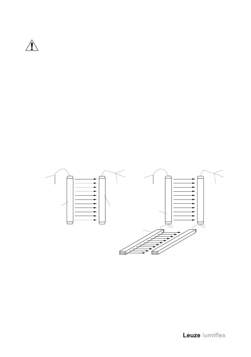
Figure 3 shows the system configuration of SCAN in both its standard design and its
master/slave version.
a = SCAN transmitter
b = SCAN receiver
c = +24V DC
d=0 V
e = +24V DC
f=0 V
g = RS 485
h = SCAN transmitter master
i = SCAN transmitter slave
Fig. 2: SCAN Standard Configuration or Master/Slave Version
a b
i
h
f
e
g
d
c
e
f
g
d
c
 Loading...