SCAN 7
SPANISCH ITALIENISCH FRANZÖSISCH ENGLISCH DEUTSCH
3.2 Function
After the supply voltage is applied, the infrared light axes are controlled and evaluated
individually in quick succession. The measurement value of each light axis (“light path
unobstructed” or “light path interrupted”) is output either as an aggregate signal at the
switch output or as a single measurement value within a serial data stream via the RS
485 interface of the receiver.
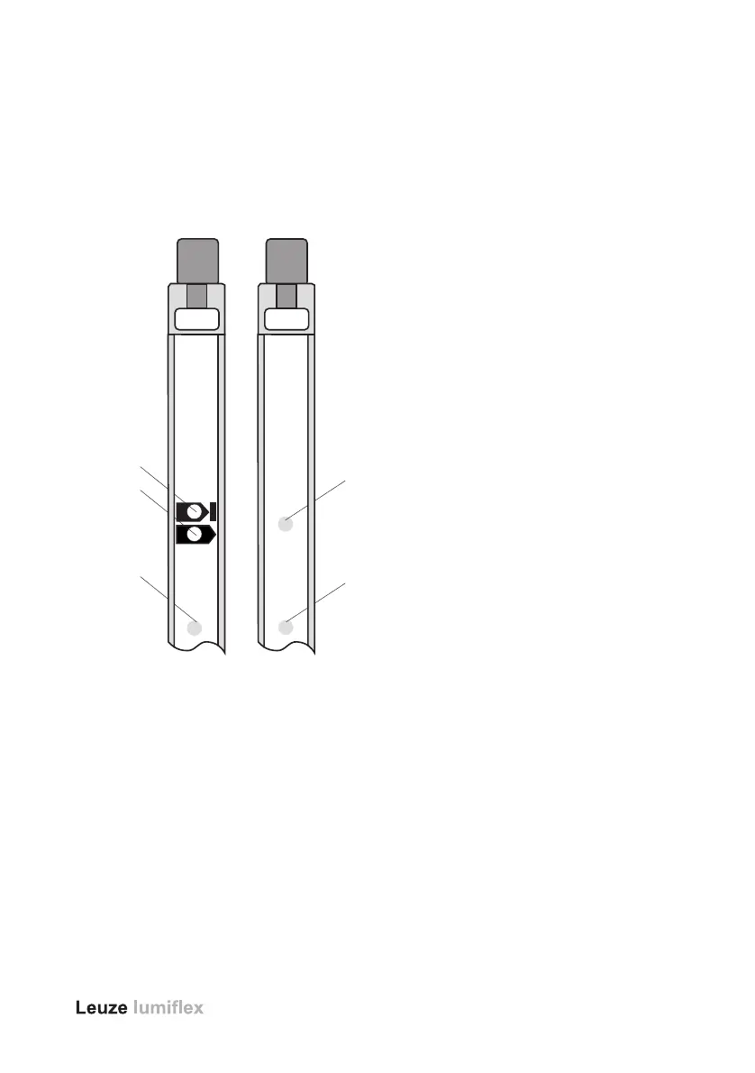
3.3 Display Elements
3.4 Switch Output Measurement Field Status
The short-circuit-proof +24V DC pnp switch output on the receiver is able to switch
earthed loads of up to 0.1 A. Contactors or relays must be wired parallel to the coil with
suitable components for suppressing interference.
a = Object in the measurement field or device out of alignment
b = Measurement field unobstructed
c = Failure in the receiver
d = Supply voltage / Transmitter on
e = Failure in the transmitter
Fig. 3: Display Elements
transmitter
Vor Anschluss
Betriebsanleitung
beachten!
Pay attention to
manual prior to
installation!
power
failure
Vor Anschluß
Betriebsanleitung
beachten!
Pay attention to
manual prior to
installation!
d
e
a
b
c
SCAN
receiver
SCAN
failure
 Loading...