INSTALLATION
WARNINGS & CAUTIONS:
• TOBEINSTALLEDAND/ORUSEDINACCORDANCEWITHELECTRICALCODESANDREGULATIONS.
• INSTALLATIONOFCAT.NOS.51120-1AND51120-3SPDDEVICESINABRANCHCIRCUITMUSTBEDONEBYANELECTRICIAN.
• READALLINSTRUCTIONSBEFOREINSTALLING.
• CAT.NOS.51120-1AND51120-3SPDDEVICESMUSTBEINSTALLEDONALINETHATISSERVEDBYDISCONNECTMEANS,SUCHAS20-AMPCIRCUITBREAKERSOR20-AMP
FUSEDDISCONNECTSWITCHES.
• SPDMAYNOTSURVIVESUSTAINEDOVERVOLTAGES.
• USETHISDEVICEONLY WITH COPPER OR COPPER CLAD WIRE.
FEATURES:
• UL1449Listed-Type2SPD
• IEEEC62.41-1991categoryA&Bcombinationwavesuppression
• Solid-statesemiconductorSPDcircuitryforeachphase
• Eachphaseindependentlyfused
• GreenLEDdiagnosticindicatorforeachphase
• NEMA1metalenclosure
• Pre-punchedstandardknockouts
• Interiorplasticcircuitenclosureforaddedsafety
• Flushmountingenclosure
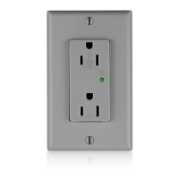
ForsuperiorlocalSPDprotection,useLevitonSurgeSuppressionOutletstoprotectagainstinternally-generatedtransientsbetweenthebranchpanelandthepointofuse.
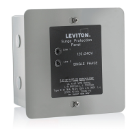
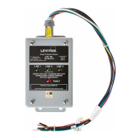
DESCRIPTION:
Leviton’sCatalogNos.51120-1(120/240V,single-phaseversion)andthe51120-3(120/208V,3-phaseversion)BranchPanelMountedSPDdeviceshavebeendesignedtoprotect
residentialandsmallcommercialestablishmentsfromhighvoltagetransients.ThestandardJ-Boxmetalenclosurewithpre-punchedstandardsizeknockoutssimpliesush
mountingintypicalframeconstructionenvironments,andprovidesconvenientconnectionmeanstoexistingbranchpanels.
TO INSTALL:
System Voltage Requirements
1. Measurepanelvoltage,L-N,todeterminethesystemvoltage.SystemvoltagemustnotexceedthespeciedmaximumcontinuousRMSvoltageontheSPDdevicelabel.
Location and Mounting
1. LocatetheSPDdeviceascloseaspossibletothebranchcircuitbreakerpanel.ConnectionleadlengthbetweentheSPDdeviceandcircuitbreakerboxshouldbeminimalfor
bestprotection.ThelocationshouldalsopermitgoodvisibilityoftheSPDdevice’sdiagnosticlights.
2. Removethecircuitbreakerpanelcoveranddeterminethebreaker-panelwiringentrypointrelativetochosenlocationoftheSPDdevice.
NOTE:SincethecircuitbreakerpanelandtheSPDunithaveoverlappingcovers,installationshouldallowatleastoneinchofclearancefromtheedgeofthecircuitbreaker
panelcover.
3. Forsurface-mountcircuitbreakerpanels,theSPDdevicemaybeconnectedusingrigidconduittoanyconduitknockouthole.
4. Fornon-surfacemountinstallations,securetheSPDtothesupportstudinthewallbycuttinga6x6-inchmountinghole.
5. RemoveSPD’scoverandconnect3/4-inchexibleorrigidconduitbetweencircuitbreakerboxandtheSPD.
6. PlacetheSPDdeviceintothe6x6-inchmountingholeandsecureittotheexposedstuds.
Wiring Connections
TheSPDdeviceterminalblockaccepts4AWG–12AWGCOPPERWIREONLY.ForwirerangeSolidorStranded12AWGto10AWGuseTorque25in-lbs.For8AWGStranded
wireuse30in-lbs.ForStranded6AWG–4AWGuse35in-lbs.
1.
WARNING:TOAVOIDFIRE,SHOCKORDEATH,TURN OFF POWERATCIRCUITBREAKERORFUSEANDTESTTHATPOWERISOFFBEFOREWIRING!
2. Connectwireleadstoterminalblock:BLACKtoPHASES,WHITEtoNEUTRALandGREENtoGROUND.SeeFigures 1through4onreverseside.
CAUTION:Ifplasticconduitisused,Greengroundwiremustbeconnectedtogroundlug,andGreenwireinsideenclosuremustalsobeconnectedtogroundlug.Failuretodo
somayresultinreorshock.SeeFig. 1,Fig. 2,Fig. 3andFig. 4onreversesideforinstallationdiagrams.
3. ThreadtheSPDdevice’swireleadsthroughtheconduittocircuitbreakerinterior.
4. SecuretheSPDcoverwiththescrewsremovedpreviously.
5. Selectcircuitbreakersascloseaspossibletoeachserviceentrancelug.Twenty-Amp(20A)circuitbreakersarerecommended,andmayshareSPDdeviceandbranchcircuit
leads.ThebreakersprovideadditionalfailureprotectionaswellasaSPDconnectionandservicingdisconnect.
NOTE:DonotconnectSPDleadsdirectlytoserviceentrancelugs.Thismayresultinre,shockordeath.
6. Leadlengthsshouldbeasshortaspossible.ConnecttheBLACKleadstoeachPHASEthroughtheselectedcircuitbreakers.ConnecttheWHITEleadtoNEUTRALascloseas
possibletoNEUTRALentranceservicelug.
NOTE: Avoidlongloopsanddonotcoilextraleadwire.
7. Replacethecircuitbreakerpanelcover.Installationiscomplete.
Power ON
1. Restorepowertocircuitbreakerpanel.ThegreendiagnosticlightsontheSPDdeviceshouldturnON.
2. Ifduringnormaloperationadiagnosticlightshutsoff,haveanelectriciandetermineifphasepowerisapplied.Ifpowerispresent,thenatransientsurgehasexceededtheSPD
device’srating.Theunitshouldbereplacedand/orupgradedassoonaspossible.
BRANCH PANEL MOUNTED SURGE PROTECTIVE DEVICE (SPD)
Cat. Nos. 51120-1&51120-3
DI-000-51120-00E