Do you have a question about the Leviton R Series and is the answer not in the manual?
Details pre-installation steps including environment, wiring, and specific considerations.
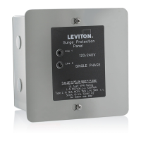
Details enclosure types and operational temperature/humidity limits.
Explains installation location requirements for Type 1 and Type 2 SPDs.
Notes that SPD background noise is negligible and does not restrict location.
Guidance on minimizing parasitic losses by locating SPDs close to circuits and using short, straight leads.
Ensures the SPD's voltage rating matches the power distribution system before installation.
Recommendation for connecting load-side SPDs via a circuit breaker for protection.
Emphasizes the use of an equipment grounding conductor and single-point ground system for best performance.
Instructions for retrofitting SPDs into panels lacking breaker positions, considering NEC rules.
Key considerations before installation, including codes, SPD placement, and breaker selection.
Explains the meaning of GREEN LEDs indicating complete protection and failure indication.
Describes the audible alarm signaling suppression element failure and how to silence it.
Details the function and specifications of dry contacts for status monitoring.
Recommends periodic inspection of diagnostic indicators and keeping the SPD clean.
Information on contacting Leviton for service-related issues.
This document describes the R, P, B, and M Series Surge Protective Devices (SPDs) from Leviton, designed to safeguard electrical systems from harmful voltage surges. These devices are intended for installation by qualified electricians only, emphasizing safety precautions due to hazardous voltages within the units.
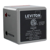
Leviton SPDs are designed to protect electrical equipment by diverting excess voltage from surges away from sensitive components. They feature internal overload protection elements and have demonstrated high Short Circuit Current Ratings (SCCRs). The R and P Series SPDs are Type 1, suitable for installation on either the line or load side of the service disconnect overcurrent device. The B and M Series SPDs are Type 2, intended for installation on the load side of the service disconnect overcurrent device. Devices with UL1293 Filtering are also Type 2.
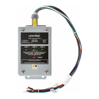
The SPDs include diagnostic indicators, specifically LEDs, to provide visual feedback on their operational status. When the LEDs are green, it signifies that complete protection is present. In the event of a Metal Oxide Varistor (MOV) stack failure, the corresponding LED will turn off, indicating a compromised protection mode.
In addition to visual indicators, the SPDs are equipped with an audible alarm. This alarm will sound upon the failure of a suppression element, mirroring the LED indication. The alarm can only be silenced by removing power to the SPD via its breaker. However, removing power will leave the system unprotected.
For remote monitoring, the SPDs incorporate dry contacts. These contacts consist of three #22 AWG wires and change state when any suppression element reaches its end of life or when power is lost. This feature allows for the monitoring of the SPD's status from a remote location. The dry contacts are designed for low-voltage or control signals only, with a maximum switching current of 2A and a maximum switching voltage of 240V AC. For higher energy applications, additional relay implementation outside the SPD is required. The WHITE wire is Common, BLACK is Normally Open, and BROWN is Normally Closed. If the dry contacts are not utilized, it is recommended to insulate the lead ends, coil, and secure them.
Proper installation is crucial for maximizing SPD performance. SPDs should be located as close to the circuit as possible, utilizing the shortest and straightest possible leads to minimize parasitic losses. For new construction, breaker locations should be adjusted accordingly. If longer leads are unavoidable, they should be gently twisted (one to two twists per foot) or tie-wrapped together.
Before installation, it is essential to verify that the SPD's voltage rating matches the power distribution system. The SPD's nameplate voltage or model number and configuration must align with the intended power source.
When connecting the SPD on the load side of the main disconnect, it is recommended to connect via a circuit breaker. This breaker serves as the intended disconnect switch and provides short circuit protection for the connecting conductors.
An equipment grounding conductor must be used on all electrical circuits connected to the SPD. For optimal performance, a single-point ground system is recommended, where the service entrance grounding electrode system is connected and bonded to all other available electrodes, building steel, metal water pipes, and driven rods. For sensitive electronics and computer systems, the ground impedance measurement should be as low as possible. If metallic raceway is used as an additional grounding conductor, an insulated grounding conductor should be run inside the raceway, ensuring adequate electrical continuity at all raceway connections. A separate isolated ground for the SPD is not recommended. On 4-Wire Power Systems, neutral-to-ground bonding (Main Bonding Jumper) must be installed per the NEC; failure to do so will damage the SPDs.
For retrofitting into existing panels without available breaker positions, applicable codes must be followed. Consolidating loads to free up breaker positions is an option. A 10 ft tap rule in NEC 240.21(B)(1) allows tapping the bus if the tap conductors are rated at least 10% of the panel's ampacity. If the panel's ampacity is larger than the SPD's wires, the bus can be tapped per NEC 240.21(B)(1), running appropriate size conductors to a safety switch fused to 30A. The SPD should then be mounted immediately adjacent to the safety switch.
Pre-installation planning includes meeting all National and Local codes (NEC Article 285 addresses SPDs), mounting the SPD as close to the panel or equipment as possible to keep leads short, ensuring leads are as short and straight as possible (including neutral and ground), considering breaker positions closest to the SPD and the panel's neutral and ground wires. Suggested breaker sizes are 20A for the R, P, and B Series, and 30A for the M Series. The system must be grounded per NEC and clear of faults before energizing the SPD.
Installation involves checking all voltages with a voltmeter, pre-planning dry contact installation, turning off power at the panel, confirming de-energization, identifying connection and breaker locations, and ensuring short leads. An appropriately-sized knockout should be removed from the panel. The SPD is then mounted, connecting to equipment using an approved wiring method, including seals appropriate for the enclosure rating. Conductors should be connected as short and straight as possible. Hi-Legs are Phase B (ORANGE). Conductors should be labeled or marked as appropriate: BLACK for Energized, WHITE for Neutral, GREEN for Ground, and ORANGE for Hi-Leg (Delta units only). The system must be bonded per NEC and clear of hazards or faults before energizing. Finally, energize and confirm proper operation of indicators and/or options. If the Audible Alarm cycles, power must be turned off immediately, and Leviton should be contacted.
Leviton SPDs require minimal maintenance. Periodic inspection of diagnostic indicators is recommended to ensure proper operation. Keeping the SPD clean is also advised. For any service-related issues, Leviton customer support should be contacted.
| Series | R Series |
|---|---|
| Category | Surge Protector |
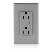
| Protection Modes | L-N, L-G, N-G |
| Amperage | 15 Amps |
| Number of Outlets | 6 |
| Cord Length | 6 feet |
| Response Time | Less than 1 nanosecond |
| Warranty | Lifetime |