2 3
Pre-Installation Continued
Lead Lengths and Maximizing SPD Performance
SPDs must be located as close to the circuit as possible to minimize parasitic losses. Use the shortest and straightest possible leads for pre-plan
installations and ensure that nearest breaker positions are used. If new construction, adjust breaker locations as appropriate. When longer leads
are unavoidable, gently twist leads together (one to two twists per foot), or tie-wrap leads together.
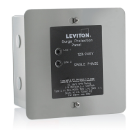
Voltage Rating
Before installing the SPD, verify that it has the same voltage rating as the power distribution system. Compare the SPDs nameplate voltage or
model number and ensure that SPD conguration matches the intended power source.
Circuit Breaker Connected
When connected on the load side of the main disconnect, we suggest connecting via a circuit breaker. The circuit breaker is the intended
disconnect switch and provides short circuit protection to the connecting conductors. These SPDs have internal overload protection elements
within the product. These SPDs have demonstrated 200kA Short Circuit Current Ratings (SCCRs).
Operating Environment Continued
System Grounding
An equipment grounding conductor must be used on all electrical circuits connected to the SPD. For the best performance, use a single point
ground system where the service entrance grounding electrode system is connected to and bonded to all other available electrodes, building steel,
metal water pipes, driven rods, etc. (For reference see, IEEE Std 142-2007.) For sensitive electronics and computer systems, we recommend that
the ground impedance measurement be as low as possible.
When metallic raceway is used as an additional grounding conductor, an insulated grounding conductor should be run inside the raceway.
Adequate electrical continuity must be maintained at all raceway connections. A separate isolated ground for the SPD is NOT recommended.
Proper equipment connections to the grounding system and ground grid continuity should be veried via inspections and testing on a regular
basis, as part of a comprehensive electrical maintenance program. On 4-Wire Power Systems, neutral to ground bonding (Main Bonding Jumper)
must be installed per the NEC. Failure to do so, WILL damage SPDs.
Retrot into Existing Panel with No Available Breaker Positions
Follow all applicable codes: Consider consolidating loads that might free breaker positions. A 10 ft tap rule in NEC 240.21(B)(1), allows you to
tap the bus as long as the tap conductors are rated at least 10% of the ampacity of the panel. In the case where the ampacity of the panel is larger
than the wires of the SPD, consider tapping the bus per NEC 240.21(B)(1) and running appropriate size conductors to a safety switch fused to
30A.
Mount the SPD immediately adjacent to the safety switch.
Installation
Pre-Plan Your Installation
• Meet all National and Local codes (NEC Article 285 addresses SPDs).
• Mount SPD as close to panel or equipment as possible to keep leads short.
• Ensure leads are as short and straight as possible, including neutral and ground.
• Consider breaker positions that are closest to the SPD and the panel’s neutral and ground wires.
• Suggested breaker size for the R, P, and B Series is 20A, and 30A for the M Series.
• Make sure system is grounded per NEC and clear of faults before energizing SPD.
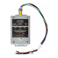
BLACK
WHITE
GREEN
BLACK
BROWN
GROUND
NEUTRAL
LINES
Connect to Alarming
Connect to Mains
Common
NC (Normally Closed)
NO (Normally Open)
WHITE
Installation Instructions
1. Use a voltmeter to check all voltages to ensure correct SPD.
2. If SPD has Dry Contact, pre-plan its installation.
3. Turn OFF power at panel. Conrm panel is de-energized.
4. Identify connection and breaker location and SPD location.
5. Make sure leads are short.
6. Remove an appropriately-sized knockout from panel.
7. Mount SPD. Connect to equipment using an approved wiring method, including seals appropriate for the enclosure rating.
8. Connect conductors as appropriate – short and straight as possible.
NOTE: Hi-Legs are Phase B (ORANGE).
9. Label or mark conductors, as appropriate.
Energized: BLACK
Neutral: WHITE
Ground: GREEN
Hi-Leg (Delta units only): ORANGE
10. Make sure system is bonded per NEC and is clear of hazards or faults before energizing. (N-G bonding, not per NEC, will fail SPDs.)
11. Energize and conrm proper operation of indicators and/or options. If Audible Alarm cycles, turn OFF power immediately and contact Leviton
at 1-800-824-3005 for help.
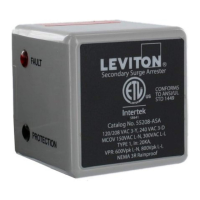
Operation
LED Operation
• When the LEDs are GREEN, complete protection is present.
• Upon a MOV stack failure, the LED that corresponds to the failed mode turns OFF.
Audible Alarm
Similar to the LEDs, the audible alarm will sound upon a suppression element failure. The alarm can be silenced only by removing power to the
SPD via the breaker. Removing power leaves the system unprotected.
Dry Contacts
Three, #22 AWG wires are included through the nipple as dry contacts. Dry contacts change state when any suppression element reaches end of
life, including the loss of power. Any change in status can be monitored elsewhere via the dry contacts.
NOTES:
• Dry contacts are designed for low-voltage or control signals only.
• Maximum switching current is 2A.
• Maximum switching voltage is 240V AC.
• Higher energy applications require additional relay implementation outside the SPD.
• WHITE is Common, BLACK is Normally Open, and BROWN is Normally Closed.
• If the dry contacts are not used, insulate the lead ends, coil, and secure.
Maintenance
SPDs require minimal maintenance. We recommend periodic inspection of diagnostic indicators to ensure proper operation. We also recommend
keeping the SPD clean, as appropriate.
Troubleshooting
Please contact Leviton for any service-related issues at 1-800-824-3005.
 Loading...