Preparing and connecting wires:
Pull off pre-cut insulation from timer switch leads. Make sure
that the ends of the wires from the wallbox are straight (cut if
necessary). Remove insulation from each wire in the wallbox as
shown:
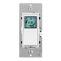
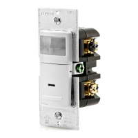
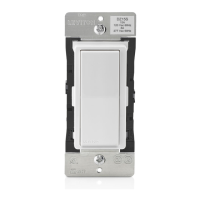
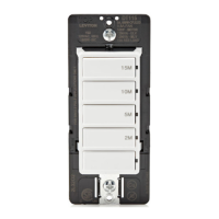
Single Pole (One Location) or 3-Way (Multi Location)
Electronic Countdown Timer Switch
Cat. No. LTB15, LTB30, LTB60, LTB02, LTB04, LTB12 Lighted
20A Resistive/Inductive, 1,800 W Incandescent/Halogen, 600 W LED/CFL, 1 HP
120 VAC, 60 Hz
WARNINGS:
• TO AVOID FIRE SHOCK OR DEATH; TURN OFF POWER at circuit breaker or fuse and test that
power is OFF before wiring!
• To be installed and/or used in accordance with appropriate electrical codes and regulations.
• If you are unsure about any part of these instructions, consult an electrician.
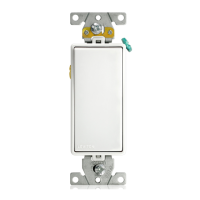
• Leviton electronic countdown timer switches are not compatible with standard 3-way or 4-way
switches. They must be used with compatible Decora
®
Wired Switch Companion (VP0SR).
• DO NOT use to control lighting if it is the only light source in the area.
CAUTIONS:
• Disconnect power at circuit breaker or fuse when servicing, installing or removing fixture.
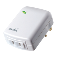
• Use only one (1) Leviton electronic countdown timer switch in a multi-location circuit with up to 9 Wired Switch Companions (VP0SR-10) or up to 4 Wired Switch Companions (VP0SR-1L).
• Maximum wire length from Timer Switch to all installed
Wired Switch Companions
cannot exceed 300 ft (90 m).
• Use this device only with copper or copper-clad wire only.
• Recommended minimum wallbox depth is 2-1/2 in.
• To avoid damage to the product, DO NOT use disinfecting products, including foggers, sprays or other types of atomized cleaning agents. DO NOT spray liquid onto the product.
To clean use a damp cloth with mild soap.
IMPORTANT: For 3-way applications, note that one of the screw terminals
from the old switch being removed will usually be a different color (Black)
or labeled Common. Tag that wire with electrical tape and identify as
the common (Line or Load) in both the switch wallbox and Wired Switch
Companion wallbox.
TOOLS NEEDED TO INSTALL YOUR TIMER SWITCH
Slotted/Phillips Screwdriver Electrical Tape Pliers
Pencil Cutters Ruler
WIRING TIMER SWITCH:
Connect wires per WIRING DIAGRAM as follows:
• Green or bare copper wire in wallbox to Green lead.
• Line Hot wallbox wire to Black lead.
• Load wallbox wire to Red lead.
• Line Neutral wallbox wire to White lead.
• Timer Switch Yellow/Red lead should have Red insulation label affixed.
• Proceed to Step 5.
Neutral (White)
YL/RD
YL/RD
RD
WH
RD
BK Hot (Black)
Black
BKWH
White
Line
120VAC, 60Hz
Green
Ground
Green
Ground
(unused)
(unused)
Load
Timer SwitchWired Switch Companion
(VP0SR-10)
BK - Black
WH - White
YL/RD - Yellow/Red
RD - Red
WIRING TIMER SWITCH:
Connect wires per WIRING DIAGRAM as follows:
NOTE: The timer switch must be installed in a wallbox that has a Line
Hot connection.
NOTE: Maximum wire length from timer switch to all installed Wired
Switch Companion devices cannot exceed 300 ft (90 m).
• Green or bare copper wire in wallbox to Green lead.
• Line Hot (common) wallbox wire identified (tagged) when removing old
switch to Black lead.
• First Traveler wallbox wire to Red lead (note wire color).
• Remove Red insulating label from Yellow/Red lead.
• Second Traveler wallbox wire to Yellow/Red lead (note wire color).
This traveler from the timer switch must go to the terminal screw on the
Wired Switch Companion marked "YL/RD."
• Line Neutral wallbox wire to White lead.
WIRING WIRED SWITCH COMPANION (VP0SR-10):
Connect wires per WIRING DIAGRAM as follows:
NOTE: "BK" and "RD" terminals on Wired Switch Companion
(VP0SR-10) are unused. Tighten both screws.
NOTE: Maximum wire length from timer switch to last Wired Switch
Companion is 300 ft (90 m).
• Green or bare copper wire in wallbox to Green terminal screw.
• Load wallbox wire identified (tagged) when removing old switch to First
Traveler (note color as above).
• Second Traveler wallbox wire (note color as above) to terminal screw
marked "YL/RD." This traveler from the Wired Switch Companion must
go to the Yellow/Red lead of the timer switch.
• Remove White insulating label from terminal screw marked "WH."
• Line Neutral wallbox wire to terminal screw marked "WH."
• Proceed to Step 5.
/./&&
/./&&
/./&&
/./&&
/./&&
/./&&
/./&&/./&&
/./&&
/./&&
/./&&
/./&&
WARNING: TO AVOID FIRE SHOCK OR DEATH; TURN
OFF POWER at circuit breaker or fuse and test that power is
off before wiring!
Step 1
2
4
3
1
2
4
1
5
3
Single Pole
1. Line (Hot)
2. Neutral
3. Ground
4. Load
3-Way
1. Line or Load
(see
IMPORTANT
instruction)
2. Neutral
3. Ground
4. First Traveler – note color
5. Second Traveler – note
color.
Identifying your wiring application (most common):
NOTE: If the wiring in your wallbox does not resemble any of
these configurations, consult an electrician.
Step 2
Insulating label:
This wire is used in 3-way installations only.
For single pole installations, do not remove
this insulating label.
1
2
Black
White
Red
4
Yellow/Red
Green
3
Single pole wiring application:
Step 4a
Step 4a cont'd
2
1
4
BK
RD
YL/RD
Timer Switch
5
3
1
2
Black
White
Red
4
Yellow/
Red
Green
3
5
WH
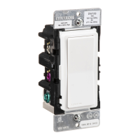
Wired Switch Companion
(VP0SR-10)
BK - Black
WH - White
YL/RD - Yellow/Red
RD - Red
3-way wiring with Wired Switch Companion
(VP0SR-10) application:
Step 4b
• Make sure that the ends of the wires from the wallbox are
straight (cut if necessary).
• Remove insulation from each wire in the wallbox as shown.
• For single pole application, go to Step 4a.
• For 3-way Wired Switch Companion (without LED) application, go to Step 4b.
• For 3-Way Wired Switch Companion (with LED) application, go to Step 4c.
Step 3
5/8 in.
(1.6 cm)
Strip Gage
(measure bare
wire here)
Cut
(if necessary)
Step 4b cont'd
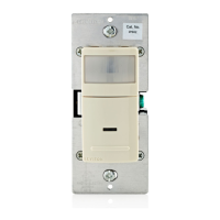
Changing the color of your device:
Your device may include color options. To change color of the face,
proceed as follows:
Color change kits available in White (W), Light Almond (T), Ivory (I),
Brown (B), Black (E), (LTBKT-00x)
Push in side
at tab to release
Line up tabs and
press in sides one
at a time to attach
For non-standard wiring applications, refer to
Wire Nut and Connector Size Chart
WIRE CONNECTOR / # OF COND. COMBINATION CHART
1 - #12 w/ 1 to 3 #14, #16 or #18
2 - #12 w/ 1 to 2 #16 or #18
1 - #14 w/ 1 to 4 #16 or #18
2 - #14 w/ 1 to 3 #16 or #18
Timer Switch
Insulating
Label
Black
Hot (Black)Black
Line
120 VAC, 60Hz
Neutral (White)
Red Yellow/Red
White
White
Green
Ground
Load
INSTALLING YOUR TIMER SWITCH
MAXIMUM LOAD PER TIMER FOR MULTI-DEVICE INSTALLATIONS
Load Single Two or more devices
Resistive Load 20A (2400 W) 16A (1920 W)
Incandescent/Halogen
1800 W 1800 W
Inductive Load 20A 16A
Motor Load 1 HP 1 HP
LED/CFL load 600 W 600 W
NOTE: For Wired Switch Companions (with
LED) the First Traveler becomes Line Hot.
PK-93796-10-00-2C