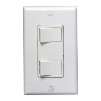
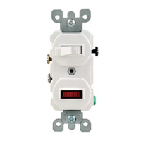
Single Pole and 3-Way Switch
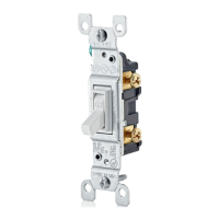
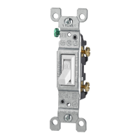
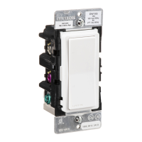
Standard Style Cat. No. 5241
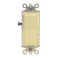
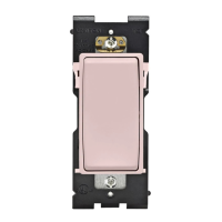
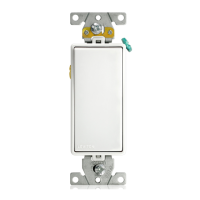
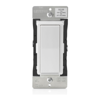
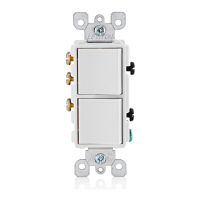
Decora Style Cat. No. 5641
Rated: 15A-120/277VAC
INSTALLATION INSTRUCTIONS
WARNINGS AND CAUTIONS:
• To be installed and/or used in accordance with appropriate electrical codes and regulations.
• To avoid fi re, shock or death, TURN OFF POWER at circuit breaker or fuse. Test that
power is off before wiring.
• Use these devices only with copper or copper clad wire. With aluminum wire use only
devices marked CO/ALR or CU/AL.
• NOTE: The following diagrams apply to both Standard Style and Decora Style
Combination Devices.
Standard Style Switch
Cat. No. 5241
Single pole
3-Way
Decora Style Switch
Cat. No. 5641
Single pole
3-Way
Tools needed to install Switch:
• Slotted, Phillips, or Robertson Screwdriver • Wire Cutters
INSTALLING SWITCH:
NOTE: Use check boxes when Steps are completed.
WARNING: To avoid fi re, shock, or death; TURN OFF POWER at circuit
breaker or fuse and test that power is off before wiring!
Step 1
/./&&
/./&&
/./&&
/./&&
/./&&
/./&&
/./&&/./&&
/./&&
/./&&
/./&&
/./&&
Identify Wall Box Wiring:
To install this combination switch, the following wires must be present
inside wall box.
Step 2
NOTE: Neutral and ground connections may differ in your application. Ensure the
device is properly grounded to system. If the wiring in the wall box does not
resemble any of these confi gurations, consult a qualifi ed electrician.
1. Line (Hot-System)
2. Neutral (Optional)
3. Ground
4. Load - Single Pole
5. Travelers (To other 3-Way Switch)
SINGLE LINE HOT
(Common Feed)
1. Line 1 (Hot-System)
2. Line 2 (Hot-System)
3. Neutral (Optional)
4. Ground
5. Load - Single Pole
6. Travelers (To other 3-Way Switch)
TWO LINE HOT
(Separate Feed))
NOTE: For separate feed (2 circuit)
operation only: The break-off
fi n located between the black
screws should be removed
before wiring. Using a standard
slotted screwdriver, bend fi n
until it breaks off.
Prepare Wires:
Remove 5/8" (1.6 cm) of insulation from each wire in the wall box.
Step 3
Installing your Switch:
COMMON FEED (Single Line Hot)
Single pole switch and 3-way switch on the same circuit. Light(s)
controlled by single pole switch, other light(s) controlled by 3-way switch
and another 3-way switch at a different location.
Step 4
PK-93604-10-00-0A
Strip 5/8"
(1.6 cm)
Strip Gage
5/8"
(1.6 cm)
" ! !
SINGLE LINE HOT
(Common Feed)
1. Line (Hot-System)
2. Neutral (Optional)
3. Ground
4. Load - Single Pole
5. Travelers (To other 3-Way Switch)