• Cat. Nos. DOS05 and DVS05 have a sensing angle of 180° and a sensing area of coverage of
30 x 30 ft. See coverage diagram for details.
• Adjustable ambient light (DOS05 only), time delay and area of coverage controls. See adjustment
setting section for details.
• Indicator light alerts the user of device status.
• Adjustable time delay setting for 1, 5, 10 and 20 minutes plus a test mode with 5 seconds on. A
Temporary Bypass mode that disables the Auto-on feature is available only for DOS05.
Single Pole and 3 Way with 3-Way Switch Application
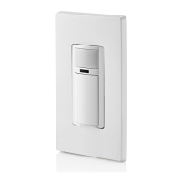
Wide View Motion Activated Light Control
Cat. Nos. DOS05, DVS05 - INDOOR USE ONLY
Ratings: 120VAC, 60Hz 600 W Incandescent, 5 A Resistive, 300W LED and CFL, 400 VA ELV/MLV, 1/4 HP Motor
INSTALLATION
ENGLISH
PK-A3346-10-00-2A-X4
WARNINGS
• TO AVOID FIRE, SHOCK OR DEATH: TURN OFF POWER AT CIRCUIT BREAKER OR FUSE AND TEST
THAT THE POWER IS OFF BEFORE WIRING!
• TO AVOID PERSONAL INJURY OR PROPERTY DAMAGE, DO NOT install to control a receptacle, or a load in
excess of the specified rating.
• To be installed and/or used in accordance with electrical codes and regulations.
• If you are not sure about any part of these instructions, consult an electrician.
CAUTIONS
• To clean use a damp cloth with mild soap. DO NOT use disinfecting products, including foggers, sprays or other
types of atomized cleaning agents.
• No user serviceable components. DO NOT attempt to service or repair.
• Use this device WITH COPPER CLAD WIRE ONLY.
Installation
WARNING: TO AVOID FIRE, SHOCK OR DEATH, turn off power at circuit breaker or fuse and test
that the power is off before wiring.
1. Identify your wires
(most common):
You Will Need:
• Slotted/Phillips screwdriver • Electrical tape
• Cutters • Pliers
Mounting Location
Features
• The device responds to temperature changes and care should be taken when mounting the device.
• DO NOT mount directly above a heat source, in a location where hot or cold drafts will blow directly
on the sensor, or where unintended motion (e.g., hallway traffic) will be within sensor's
field-of-view.
NEUTRAL
GROUND
GROUND
LOAD
LINE
GROUND
LOAD
LINE
OR
3. Test and mount.
• Restore power. Wait 10-20 seconds for sensor to power up.
• DOS05: lights will automatically turn ON with first motion seen after warm up period, or press push
pad.
• DVS05: press push pad. Lights should turn ON.
NOTE: If lights do not turn ON, refer to the "What to do if..." section.
Turn off power at circuit breaker before completing the installation.
• Gently push wires into wall box. Screw light control to box.
• Install wallplate.
• Restore power.
Single Pole
3-Way (Neutral present)
Switch Wallbox
TRAVELER 2
To Light
GROUND
GROUND
From Switch
Wallbox
LINE
TRAVELER 1
NEUTRAL
NEUTRAL
To Sensor
From
Branch Circuit
LOAD
NEUTRAL
GROUND
GROUND
NEUTRAL
TRAVELER 1
TRAVELER 2
OR
2a. Wire (when Neutral is NOT present).
Working on one connection at a time, connect wires as shown.
NOTE: This device is designed so the line and load wires can be wired interchangeably.
LINE/LOAD
(Black)
LINE
GROUND
GROUND
(Green/yellow)
LOAD
LINE/LOAD
(Black)
GROUND
(Green
sleeved wire)
TRAVELER
(Red/yellow)
Single Pole
3-Way
NOTE: To control the load from the 3-way
switch, toggle once to turn the load ON
and twice to turn the load OFF.
2b. Wire (when Neutral is present).
Remove the GREEN sleeve from the white wire. Working on one connection at a time, connect
wires as shown.
NOTE: This device is designed so the line and load wires can be wired interchangeably.
NEUTRAL
(White)
NEUTRAL
LINE/LOAD
(Black)
LINE/LOAD
(Black)
LINE
LOAD
GROUND
GROUND
(Green/yellow)
TRAVELER
(Red/yellow)
Single Pole
3-Way
NOTE: To control the load from the 3-way
switch, toggle once to turn the load ON
and twice to turn the load OFF.
3-Way (Neutral NOT present)
NOTE: Neutral wire (if present), or a Ground wire is required for operation. If the wiring in the
wall box does not resemble this configuration, consult an electrician.
NOTE: Sensor must be installed in the location where the load wire is.
Switch Wallbox
To
GROUND
From Switch Wallbox
LINE
TRAVELER 1
TRAVELER 2
To Sensor
Wallbox
From
Branch Circuit
LOAD
GROUND
TRAVELER 1
TRAVELER 2
3-Way Switch Wallbox 1
From Branch Circuit
To Light
To Sensor
Wallbox 2
From 3-Way Switch
Wallbox 1
TRAVELER 1
LINE/LOAD
(Black)
LINE/LOAD
(Black)
LOAD
LINE
GROUND
(Green/Yellow)
TRAVELER
(Red/yellow)
GROUND
(Green
sleeved wire)
TRAVELER 2
TRAVELER 1
GROUND
GROUND
TRAVELER 2
GROUND
(Green)
LINE
(Black)
LOAD
(Red)
To Sensor
Wallbox
Sensor Wallbox
To Light
From 3-Way Switch
Wallbox
3-Way Switch Wallbox
From Branch Circuit
TRAVELER 1
LINE
LOAD
LOAD
(Red)
GROUND
GROUND
GROUND
(Green)
TRAVELER 2
NEUTRAL
(White)
LINE/LOAD
(Black)
LINE/LOAD
(Black)
GROUND
(Green/Yellow)
TRAVELER 1
TRAVELER 1
(Red/yellow)
TRAVELER 2
LINE
(Black)
NEUTRAL
NEUTRAL