Sense is Normal Power through the supply Input (Black/White): In this scenario, the supply input wires
are connected to normal power, and, the Load In for the relay is connected to Emergency Power. Upon loss
of normal power, the relay closes, and the 0-10V lines go to high impedance allowing the load to go to full
output powered from the Emergency Source. The Emergency Mode switch must be in the LINE position.
Upon restoration of normal power, Smart Pack will automatically resume normal operation.
Distributed Room Controller (DRC) Smart Pack
Cat. No. DRD07
PK-A3148-10-00-2B
• To avoid electrical overload, total connected lamp load shall not exceed output rating.
• To reduce potential shock hazard Cat. No. NPRPT-002 must be installed when more than (2) DRC DRD07-EDO controllers are installed on any
LumaCAN control feed.
• The NPRPT-002 must be grounded to building ground using green wire provided on device.
CAUTIONS
• Test all LumaCAN cables for proper pin-out configuration prior to interconnecting devices and systems.
• Equipment should be mounted in locations and at heights where it will not be subjected to tampering by unauthorized personnel.
• To be installed and/or used in accordance with electrical codes and regulations.
ENGLISH
INSTALLATION AND QUICK START GUIDE
DESCRIPTION
The Distributed Room Controller Smart Pack contains a power supply, 0-10V Dimming Control, LumaCAN
RJ45 input/output and a load switching latching relay. The power supply provides Class 2 low-voltage power
over LumaCAN for powering other devices (Distributed Switch, Occupancy Sensor, Photocell, Sapphire
Touch Controller) as well as monitoring the status of power.
The DRC Smart Pack requires connection to
a LumaCAN network for control, no local control is provided.
The power pack includes zero cross switching
circuitry to minimize inrush current associated with incandescent lights, LED and electronic ballasts,
increasing its life expectancy.
Application Notes:
1. When the total lighting fixtures load exceeds a single power pack’s rating (e.g. 16A Electronic Ballasts),
the load will need to be separated using multiple DRC Smart Packs.
2. When more devices are required than one power pack can supply on the
+
24V LumaCAN bus, multiple
power packs can be used to supply power to support the additional devices (up to a maximum of 600mA
between two power packs via LumaCAN RJ45 24V output).
Total number of devices attached to a single DRC Smart Pack must be <= 300mA.
Device current requirement (typical):
Sapphire Touch Controller = 600mA (2 DRC's Required)
Digital Switch = 25mA
Photocell = 15mA
Occupancy Sensor = 40mA
WARNINGS
• TO AVOID FIRE, SHOCK, OR DEATH; TURN OFF POWER AT CIRCUIT BREAKER OR FUSE AND TEST THAT POWER IS OFF BEFORE
WIRING, SERVICING, OR REMOVING FIXTURE OR CHANGING LAMPS!
• This equipment permits more than one power supply output source. To avoid shock or death, disconnect both normal and emergency sources
connected to this unit before servicing any equipment connected to this unit.
• Do not use outdoors, or near gas or electric heaters.
• The use of accessory equipment not recommended by the manufacturer may cause an unsafe condition.
• "EMERGENCY CIRCUITS" enclosed label should be placed in a highly visible location if any DRC is part of the emergency system so as to be readily
identifiable as a component of the emergency system.
SPECIFICATIONS
Part Number DRD07-ED0
Input Voltage* 120-277VAC, 50/60Hz
Standby Power: 0.62W @ 120V, 1.08W @ 277V
Max Power: 9.30W @ 120V, 9.78W @ 277V
Load Ratings
(120-277VAC)
20A Tungsten
20A General Purpose Plug Load
20A Standard Ballast
16A Electronic Ballast, LED
Motor Ratings 1/2Hp (9.8 FLA) @ 120VAC
2 Hp (12 FLA) @ 240-277VAC
0-10V Control 0.8 - 10
+
VDC, 100mA Sinking
LumaCAN Power Output
+
24VDC, 300mA
(will not pass power through, diodes installed on each of the two RJ45’s.
Supply only.)
LumaCAN Data LumaCAN 3 Only
Daisy-Chain Topology
1600 feet max per segment
Repeaters can be used for networks up to 10,000 feet and to support
home-run topology
Max 110 nodes per segment
Max 250 nodes
Connections 18 AWG (Power, 0-10V)
12 AWG (Load IN/OUT)
RJ45, CAT6A or better (LumaCAN)
LED Indicator Yes
Dimensions 4.84" x 4.52" x 1.81"
Weight 0.6 lb (9 oz)
Mounting Standard 4S junction box with minimum volume of 30.3 cu. inches or
greater (4" x 4"x 2.125") using the two (2) provided 8-32 x 2.5" screws.
Or, mounted to junction box via 1/2" nipple.
LumaCAN Connections CAT6A (or better) cable
Operational Temperature 32° to 122º F (0° to 50° C)
Agency Standards and
Certifications
FCC Part 15, Class A
IEC 61000 4-2, 2nd Ed., 12kV Air (ESD)
IEC 61000 4-5, 3rd Ed., 2/4kV (Line Surge)
IP Rating IP30
* Input voltage tolerance 10%, Frequency tolerance 5%.
EMERGENCY
The "Emergency Circuits" label shall be placed on the Smart Pack so the user is aware this device is used
for emergency lighting.
The DRC Smart Pack can be used as a UL 924 emergency bypass device ensuring that the relay is closed
during a power failure condition. Availability of input power to power the load is the responsibility of others. Two
options for sensing normal power are available and your Construction Documents will dictate which you are to
use. The options and features of normal sense are as follows:
• Sense is Normal Power through the Black (Line) wire: Upon loss of supplying power to the device,
relay will close.
• Sense is power over LumaCAN: Upon loss of +24V power on LumaCAN wire, relay will close.
Sense is power over LumaCAN: In this scenario, both the supply input wires AND the Load-In are connected
to the emergency source. The SmartPack monitors power on the LumaCAN line and upon loss of power, the
relay closes and 0-10V lines go to full output. There are two advantages of this mode: 1. LumaCAN remains
operational during the emergency event and can report it’s status to the network, and, 2. Only EM power is run
to the DRC Smart Pack so separation of normal and emergency at this location is not required.
INSTALLATION
1. WARNING: TO AVOID FIRE, SHOCK, OR DEATH; TURN OFF POWER AT CIRCUIT BREAKER OR
FUSE AND TEST THAT POWER IS OFF BEFORE WIRING!
NOTE: This is an ESD Sensitive Device. Use safe ESD handling procedures when installing.
2. Mount the DRC Smart pack per desired application (see Mounting figure):
a. Mount to junction box using nipple and mounting nut provided.
b. Mount to face of 4S junction box with minimum volume 30.3 cu. inches or greater (4" x 4"x 2.125")
using the two (2) provided 8-32 x 2.5" screws.
• Ensure that conduit/cable entry clamp is located in a corner of junction box opposite the DRC
nipple as conflicts may occur.
• Dress wires to provide enough clearance when device is installed.
3. INSTALLATION NOTE: 0-10V Control Wiring - Connect the Violet wire to the + 0-10V line and the Gray
wire to the 0-10V common using Class 1 or Class 2 wiring methods as indicated in these instructions,
ballast/fixture/driver instructions or ballast/fixture/driver label markings which are in accordance with
NEC Code NFPA 70, paragraph 725.136 (d).
a. For Installation as a Class 1 Device: When this product is installed as a Class 1 device and
configured for use with other Class 1 devices it shall be wired using typical NEC Class 1 requirements.
b. For Installation as a Class 2 Device:
NOTE: Class 2 Installation must be implemented when installing this product.
As required under NEC code NFPA 70, paragraph 725.136 (d), the Class 2 0-10V (gray and violet)
control wires must be mechanically separated from Class 1 wiring (line, neutral and ground power
lines) when located within the same electrical box. This is accomplished by installing a mechanical
barrier such as silicone tubing or other non-conducting sleeve over the length of 0-10V control wires.
Restore power at circuit breaker or fuse. INSTALLATION IS COMPLETE. When power is applied, Smart
Pack will power up in the ON state and then default to the last powered down state. The default from the
factory is ON after power up.
Wire Designations
Control Power In: 120-277VAC Black 18 AWG
Control Neutral White 18 AWG
Load (Load IN) Blue/White 12 AWG
Load (Load OUT) Blue 12 AWG
0-10VDC Control Violet 18 AWG
0-10VDC Common Gray 18 AWG
• All wires rated at 105C, 600V insulation.
1. LINE - Black is tied to 120-277VAC Line power (Black incoming line)
2. Neutral - White is tied to incoming Neutral
3. LOAD IN - Blue/White is the input/incoming Load line is tied to incoming "LINE" power. This could be
same wire as #1 or it could be a separate "LINE" power. Perhaps coming from Emergency circuit supply.
Can be 120-277VAC.
4. LOAD OUT - Blue wire. This goes to the device to be powered.
5. The Violet gets connected to the + side of the fixture's 0-10V dimming input and Gray gets connected to
the – side of the fixture's 0-10V dimming input.
LumaCAN LumaCAN
Neutral
Hot
HotWhite
Black
Blue/
White
Neutral
Neutral (white)
0-10V (violet)
Com (gray)
Hot (blue)
Smart
Pack
To Load
Normal
Panel
Emergency
Panel
4. Line Voltage Wiring: Remove 5/8" (1.6 cm) of insulation from each circuit conductor. Make sure that
ends of conductors are straight. Connect lead wires from DRC Smart Pack to LINE circuit per appropriate
WIRING DIAGRAM as follows: Twist strands of each lead tightly and, with circuit conductors push firmly
into appropriate wire connector. Screw connectors on clockwise making sure that no bare conductor
shows below the wire connectors. Secure each connector with electrical tape.
5. LumaCAN: Two LumaCAN ports are provided to maintain the required Daisy-Chain topology of the
LumaCAN network. Plug in CAT6A (or better) cable with standard RJ45 connector. If two connections
are required, remove the terminator from one of the RJ45’s and make both connections. If only one
connection is required, leave the supplied terminator connected.
• Wire per the TIA-568B standard.
• The sequence of network nodes, as described in the Construction Documents, may be critical to
ensure power distribution between nodes.
• All LumaCAN wire segments must be tested and validated prior to power-up of the system.
• The last device in each LumaCAN run must be terminated using an RJ45 terminator plug. Each
Smart Pack is supplied with one terminator plug pre-installed in the smart pack. Additional terminators
are available upon request. LumaCAN connections must be wired as Class 2 and as such should be
installed according to the requirements of your authorities having jurisdiction. If it is required that the
Class 2 wiring be in conduit, use a 4S extension ring and blank plate on the LumaCAN side of the
Smart Pack, and, terminate conduit to the extension ring.
MOUNTING
a) b)
Nipple
Mounting Screws
1. LumaCAN Port
2. LumaCAN LED - left side of DIP switch
3. Heartbeat/Configuration LED - right side of DIP switch
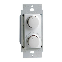
4. DIP Switches - In middle
5. Emergency Sense Selector Switch - At bottom of tub. (LINE MODE = AWAY from RJ45
CONNECTORS, CAN MODE = CLOSE to RJ45 CONNECTORS)
LED INDICATORS
The LumaCAN LED: Flashes Green whenever there is LumaCAN traffic detected.
Heartbeat LED: See chart below:
Heartbeat LED status in various "failure" states are as follows:
• Processor fails or failed application - RED
- Resolution: Cycle Power. If a power cycle does not restore proper operation, remove LumaCAN
connections and cycle power again. Do not reconnect LumaCAN until after normal operation is
restored.
• Processor in Reset or startup failure - WHITE
- Resolution: Cycle Power. If a power cycle does not restore proper operation, remove LumaCAN
connections and cycle power again. Do not reconnect LumaCAN until after normal operation is
restored.
• Off - Failure
- Resolution: Remove LumaCAN wires. If devices starts up, then there is either an Overcurrent or
Short on the LumaCAN line. Resolve the problem and reconnect.
- Resolution: Check Control Power Input. If Control Power Input is not valid, the device will not
start. Set CAN address to 255 and cycle power to erase application, then reprogram.
OPERATION
3
2
1 1
4
5
Indicator Feature
Blink Rate
(# blinks
per
second)
Duration Possible Causes
Red Duplicate LumaCAN
address
UI Error didn't get
value set in time
External watchdog fail
safe circuit tripped.
2
8
Solid
Until conflict is
resolved
Until 60 seconds or UI
setting restarted
Until watchdog circuit
is no longer tripped
Another LumaCAN device
is using the same address
T
ook too long to enter
manual information
Application update failure,
hardware failure
White LumaCAN address
on switch matches
current address
Setting LumaCAN
address and verifying
address uniqueness
Device didn’t start, I/O
not initialized
8
Solid
Solid
Until set or timed out
after 10 seconds
Until timed out after
10 seconds
Until problem resolved
Hardware failure
Blue Low byte of LumaCAN
channel number is
locked in
Waiting for low byte to
be locked in
8
Solid Until set or timed out
after 60 seconds
Green Normal operating
condition
In boot loader
High byte of
LumaCAN channel
number is locked in
Waiting for high byte
to be locked in
1
4
8
Solid
Until entering actual
application
Single blink
Until set or timed out
after 60 seconds
Application update failure
if alternating with RED
LED.
Off LumaCAN
Overcurrent or failure
––
• If you are not sure about any part of these instructions, consult an electrician.
• Use this device with copper or copper clad wire only.
• DRC & NPRPT-002 devices can be installed in any order.
• Providing this additional ground does not apply when connect to the GreenMAX™ control panel.
SAVE THESE INSTRUCTIONS
LumaCAN LumaCAN
Hot
Hot
WH
BLK
BL/WH
WH
BLK
BL/WH
Neutral
Neutral
Neutral (white)
Neutral (white)
0-10V (violet)
Com (gray)
Hot (blue)
Normal
Lighting
Smart
Pack
To Normal
Lighting Load
Normal
Panel
Emergency
Panel
Emergency
Lighting
Smart
Pack
0-10V (violet)
Com (gray)
Hot (blue)
To Emergency
Lighting Load
• Notes Specific to this mode:
- The Emergency Mode switch must be in the CAN position
-
The Smart Pack will not provide power to the LumaCAN network. All power must be from
other devices.
-
The Systems Designer and Installer must verify that any and all power supplies which
could supply power to either LumaCAN segment are fed from normal power and are not
connected to a UPS or other power source which could be powered in an EM condition.
-
SmartPack will go to full output within 1 second.
-
Upon restoration of Normal Power, the Smart Pack will automatically resume normal
operation.
• CAN MODE
- Device does NOT supply voltage or power to +24VDC LumaCAN bus
- On loss of +24VDC LumaCAN bus power device will close RELAY and force 0-10V to
MAX brightness
• LINE MODE
- Device supplies 24VDC power to LumaCAN bus to power other devices
- On loss of LINE power the device will close RELAY and force 0-10V to high
impedance (Max brightness)
CAN MODE
(switch in
UP position)
LINE MODE
(switch in
DOWN position)
The CAN Switch
EMERGENCY
S
ense Switch
LINE
CAN
EMERGENCY
Sense Switch
LINE
CAN
EME
R
GE
N
C
Y
Sens
e
Swi
t
c
h
LINE
CAN
1. When product is used with 120VAC power source and the 0-10V control wires are connected to CL3,
CL3R or CL3P rated control cables (or permitted substitute), then silicone tubing or other non-conducting
sleeve is required over the control wires for the entire wire length from the device to the location where
the wires exit the box. Tubing is not required on the CL3, CL3R or CL3P between the wire connector and
extending out of the electrical box.
2. When used with 277VAC power source and the 0-10V control wires are connected to CL3, CL3R or
CL3P rated control cables (or permitted substitute), then silicone tubing or other non-conducting sleeve
is required over the control wires for the entire wire length from the device to the location where the
wires exit the box. Tubing is also required on the CL3, CL3R or CL3P between the wire connector and
extending out of the electrical box.
NOTE:
• Silicone tubing should be NRTL (UL/CSA/ETL) recognized or equivalent to provide mechanical separation
equal to .25” in air.
• Connectors joining 0-10V control wires should be approved LISTED CONNECTORS.
• Wire connectors and wire tubing should be provided by the installation contractor.
Hot
0-10V (violet)
Com (gray)
Neutral
(white)
LumaCAN
Hot (blue)
Neutral
BLK
WH
BL/WH
Normal
Lighting
Smart
Pack
Normal
Panel
To Normal
Lighting Load
LumaCAN