EasyManua.ls Logo

Leviton GreenMax DRC DRC07-ED0 - User Manual

Leviton GreenMax DRC DRC07-ED0
2 pages
Print Icon
To Next Page IconTo Next Page
Loading...
The DRC Controller and Smart Pack combines all the functionality of a DRC Controller and Load
controlling Smart Pack in a single device. As with any DRC Controller, this device is responsible
for management of all the architectural controls and energy management business logic within a
VLQJOHURRPDQGLVIXOO\VHWXSDQGFRQ¿JXUHGXVLQJD:L)L
®
enabled cell phone or tablet.
The LumaCAN™ network can span multiple rooms and connect multiple DRC devices
together; however it is important to pay particular attention to setup and control of rooms to
avoid cross room control.
Each DRC Controller can connect to a variety of devices, such as DRC smart packs, relay
SDQHOVDQGLQWKHIXWXUH,QWHOOHFW¿[WXUHV/XPLQD5)VHQVRUV'$/,GHYLFHVDQGRWKHU
GHYLFHV)RUVSHFL¿FFDSDELOLWLHVDQGFDSDFLWLHVUHIHUWRWKHSURGXFWGDWDVKHHW
3. Connect LumaCAN (See port locations in Operation step 1)
7ZR/XPD&$1SRUWVDUHSURYLGHGWRPDLQWDLQWKHUHTXLUHG'DLV\&KDLQWRSRORJ\RIWKH
LumaCAN network. Plug in CAT6 cable with standard RJ45 connector. If two connections are
required, remove the terminator from one of the RJ45’s and make both connections. If only
one connection is required, leave the supplied terminator connected.
:LUHSHUWKH7,$%VWDQGDUG
The sequence of network nodes, as described in the construction documents, may be critical
to ensure power distribution between nodes.
$OO/XPD&$1FDEOHVHJPHQWVPXVWEHQHWZRUNFDEOHWHVWHGDQGYDOLGDWHGSULRUWRSRZHUXS
of the system.
The last device in each LumaCAN run must be terminated using an RJ45 terminator plug.
(DFK6PDUW3DFNLVVXSSOLHGZLWKRQHWHUPLQDWRUSOXJSUHLQVWDOOHGLQWKH6PDUW3DFN
Additional terminators are available upon request. LumaCAN connections must be wired as
Class 2 and as such should be installed according to the requirements of your authorities
having jurisdiction. If it is required that the Class 2 wiring be in conduit, use a 4 in. square
H[WHQVLRQULQJDQGEODQNSODWHRQWKH/XPD&$1VLGHRIWKH6PDUW3DFNDQGWHUPLQDWH
FRQGXLWWRWKHH[WHQVLRQULQJ
2QFHFRPSOHWHUHVWRUHSRZHUWRWKHFLUFXLWEUHDNHURUIXVH:KHQSRZHULVDSSOLHG'5&
Smart Pack will power up in the ON state and then default to the last powered down state.
The default from the factory is ON after power up.
WARNINGS
• READ AND FOLLOW ALL SAFETY INSTRUCTIONS
TO AVOID FIRE, SHOCK, OR DEATH; TURN OFF POWER AT CIRCUIT BREAKER OR FUSE AND TURN
OFF POWER AT THE 24 HOUR NIGHT LIGHT/EMERGENCY CIRCUIT AND TEST THAT POWER IN BOTH
CIRCUITS IS OFF BEFORE WIRING, SERVICING, OR REMOVING FIXTURE. THIS FIXTURE IS POWERED
BY TWO (2) CIRCUITS: THE REGULAR POWER BRANCH CIRCUIT AND THE 24 HOUR NIGHT LIGHT/
EMERGENCY CIRCUIT.
"EMERGENCY CIRCUITS" enclosed label should be placed in a highly visible location if any DRC Smart Pack
LVSDUWRIWKHHPHUJHQF\V\VWHPVRDVWREHUHDGLO\LGHQWL¿DEOHDVDFRPSRQHQWRIWKHHPHUJHQF\V\VWHP
Do not mount near gas or electric heaters.
The use of accessory equipment is not recommended by the manufacturer may cause an unsafe condition.
7RDYRLGHOHFWULFDORYHUORDGWRWDOFRQQHFWHGODPSORDGVKDOOQRWH[FHHGRXWSXWUDWLQJ
WARNINGS
7HVWDOO/XPD&$1FDEOHVIRUFRPSOLDQFHWR7,$%SULRUWRLQWHUFRQQHFWLQJGHYLFHVDQGV\VWHPV
Equipment should be mounted in locations and at heights where it will not be subjected to tampering by
unauthorized personnel.
To be installed and/or used in accordance with appropriate electrical codes and regulations.
If you are unsure about any part of these instructions, consult an electrician.
CAUTIONS
Do not use this equipment for other than intended use.
)RULQGRRUDSSOLFDWLRQVRQO\
SAVE THESE INSTRUCTIONS
WARNING: TO AVOID FIRE, SHOCK, OR DEATH; TURN OFF POWER at circuit breaker
or fuse and test that power is off before wiring!
NOTE: This is an ESD Sensitive Device. Use safe ESD handling procedures
when installing.
1. Mount.
Product Description
Installation
DRC™ Controller and Smart Pack
&DW1RV'5&(''5&(
INSTALLATION AND QUICK START SHEET
ENGLISH
','5&$
a. 0RXQWWRIDFHRILQVTMXQFWLRQER[ZLWKPLQLPXP
YROXPHFXLQRUJUHDWHULQ[LQ[LQ
using the provided screws.
NOTE the following:
Ensure that conduit/cable entry clamp is located in
DFRUQHURIMXQFWLRQER[RSSRVLWHWKH'5&QLSSOHDV
FRQÀLFWVPD\RFFXU
Dress wires to provide enough clearance when
device is installed.
b. Preferred installation method is 1a above, but the product may also be mounted using
WKHQLSSOHWKURXJKDMXQFWLRQER[NQRFNRXWNOTE: ensure all indicators remain visible
DQGDFFHVVLEOHSRVWLQVWDOODWLRQ
2. :LUH
:LUH/LQHYROWDJHDQGFRQWUROZLULQJSHUZLULQJGLDJUDP,IFRQWURO9ZLULQJLVWREHUXQ
as class 2, sleeve wires with suitable insulating material from the Smart Pack throughout until
WKH\H[LWWKHMXQFWLRQER[
Hot
0-10V (violet)
Com (gray)
Neutral
(white)
LumaCAN
Hot (blue)
Neutral
BLK
WH
WH/BL
BL/WH
Normal
Lighting
Smart
Pack
Normal
Panel
To Normal
Lighting Load
LumaCAN
Green
SPECIFICATIONS
Cat. No. '5&(' '5&(
Input Voltage/Frequency 9$&+]
347VAC, 60Hz
Input Power
0D[
:#9
:#9
12W @ 347V
Standby
:#9
:#9
2.3W @ 347V
Load Ratings
20A Tungsten
20A General Purpose Plug Load
20A Standard Ballast
16A Electronic Ballast, LED
12A Electronic Ballast, LED
Motor Ratings
1/2Hp (9.8 FLA) @ 120VAC
2 Hp (12 FLA) @ 240-277VAC
N/A
0-10V Control
0.8 - 10+VDC, 100mA Sinking
LumaCAN Data
/XPD&$12QO\
'DLV\&KDLQ7RSRORJ\
IHHWPD[SHUVHJPHQW
5HSHDWHUVFDQEHXVHGIRUQHWZRUNVXSWRIHHWDQGWRVXSSRUWKRPHUXQWRSRORJ\
0D[QRGHVSHUVHJPHQW
0D[QRGHV
Termination required at end of line, termination jumper provided
LumaCAN Power
P$3RZHU6XSSO\SURYLGHGWR/XPD&$1ZKHQ(06HQVHVZLWFKLVLQ/,1(SRVLWLRQ
:KHQ(06ZLWFKLVLQ&$1SRVLWLRQQRSRZHUVXSSOLHGWR/XPD&$1QHWZRUN
1RGLRGHVRQ5-¶VSRZHUDOZD\VSDVVHVWKURXJK
Connections
$:*3RZHU9
$:*/RDG,1287
RJ45, CAT6A or better (LumaCAN)
LED Indicator Yes
Dimensions [[
Weight 0.6 lb (9 oz)
Mounting
6WDQGDUG´VTXDUHMXQFWLRQER[ZLWKPLQLPXPYROXPHRIFXLQFKHVRUJUHDWHU
[[XVLQJWKHWZRSURYLGHG[VFUHZV2UPRXQWHGWRMXQFWLRQ
ER[YLDQLSSOH
LumaCAN Connections CAT6 cable
Operational Temperature WR)WR&
IP Rating ,3
GreenMax
®
Heartbeat Indicator
Indicator Feature
Light
Status
Possible Causes/Resolution
Red
Failed application or
processor failure
solid
Cycle power. If a power cycle does not restore proper operation, remove
LumaCAN cables and cycle power again. Do not reconnect LumaCAN
until after normal operation is restored.
Duplicate LumaCAN address blinking
Log into controller with app and change LumaCAN address to a unique
address.
White
Processor in reset or startup
failure
solid
Cycle power. If a power cycle does not restore proper operation, remove
LumaCAN cables and cycle power again. Do not reconnect LumaCAN
until after normal operation is restored.
Off Failure off
Remove LumaCAN cables. If device starts up, then there is either an
overcurrent or short on the LumaCAN cables. Resolve the problem and
reconnect. If removing cables does not solve the problem, check control
Power Input.
6
LuminaRF/Intellect/Zigbee
Switch Actions
Action Feature Result
Press/Release <1 second Status indication
2QHEOLQNQRWFRQ¿JXUHG7KUHHEOLQNVQHWZRUN
formed
10 second press Enable/disable UDSLGÀDVKHVZKHQWULJJHUHG
20 second press Reset device to factory default state 5DSLGFRQWLQXRXVÀDVKLQJUHVHWWULJJHUHGRQUHOHDVH
>25 second press LED goes dark :KHQUHOHDVHGQRDFWLRQZLOOEHWDNHQ
2
Wi-Fi Indicator
Indicator Feature
Solid GREEN
:L)LHQDEOHGQRWUDI¿F
%OLQN*5((1 1HWZRUNWUDI¿F
2)) :L)LGLVDEOHG
LumaCAN Indicator
Indicator Feature
Solid GREEN LumaCAN enabled
%OLQN*5((1 7UDI¿F
2)) LumaCAN disabled
LuminaRF/Intellect/Zigbee Indicator
Indicator Feature
Solid GREEN (QDEOHGQRWUDI¿F
%OLQN*5((1 1HWZRUNWUDI¿F
2)) Disabled
543
Indicator lights and switches (for normal operation)
Wi-Fi Switch Actions
Action Feature Result
Press/Release <1 second
(also can be done with power cycle)
5HWULJJHU66,'EURDGFDVW SSID broadcast times out after 15 minutes
10 second press (QDEOHGLVDEOH:L)L UDSLGÀDVKHVZKHQWULJJHUHG
20 second press
5HVHW:L)LQHWZRUNFRQ¿JXUDWLRQ
to factory default state
5DSLGFRQWLQXRXVÀDVKLQJUHVHWWULJJHUHGRQUHOHDVH
>25 second press LED goes dark :KHQUHOHDVHGQRDFWLRQZLOOEHWDNHQ
1
1 2 3 4 5 6
:KHQLQVWDOOLQJLQMXULVGLFWLRQVZKLFKUHTXLUH&ODVVQHWZRUNZLULQJLQFRQGXLWDGGD
LQVTXDUHH[WHQVLRQULQJRQWRSRIWKHVPDUWSDFNDQGDEODQNFRYHURQWRSRIWKDW
7KHVPDUWSDFNZLOOWKHQEHVDQGZLFKHGEHWZHHQWZRMXQFWLRQER[HVVRRQHFDQEH
used for Class 2 and the other for Class 1.
Some jurisdictions, like Chicago, may require the smart pack to be installed into a
PHWDOHQFORVXUH:KHQWKLVLVUHTXLUHGWKHFRQWUDFWRUVKDOOSURYLGHDSSURSULDWH
enclosure or request the appropriate enclosure from Leviton.
Mounting Screws
WEB VERSION
Question and Answer IconNeed help?

Do you have a question about the Leviton GreenMax DRC DRC07-ED0 and is the answer not in the manual?

Summary

Product Overview

Product Description

Combines DRC Controller and Load controlling Smart Pack functionality for architectural controls and energy management.

Installation Guide

Mounting Procedures

Instructions for mounting the DRC Smart Pack to junction boxes using screws or nipple.

Wiring Connections

Guidance on wiring line voltage, control wiring, and Class 2 network wiring.

LumaCAN Network Setup

Details on connecting LumaCAN ports for daisy-chain topology and cable requirements.

Technical Specifications

Electrical Ratings

Covers input voltage, power, load, and motor ratings for the device.

Control and Network Specs

Details 0-10V control, LumaCAN data limits, power, and connections.

Physical and Environmental

Includes dimensions, weight, mounting, operational temperature, and IP rating.

Indicators and Switches

Switch Actions

Describes actions for Wi-Fi and LuminaRF/Intellect/Zigbee switches.

Status Indicators

Explains Wi-Fi, LuminaRF/Intellect/Zigbee, LumaCAN, and Heartbeat indicator lights.

Emergency Operation Modes

Line Mode Operation

Details operation where power loss is sensed via the normal power line.

CAN Mode Operation

Details operation where power loss is sensed via the LumaCAN power.

Configuration Settings

Controller Configuration

Steps for configuring the DRC controller using a Wi-Fi enabled device and the Leviton app.

Network Configuration Changes

Procedure to reset network settings and reconnect if wireless configuration changes.

Troubleshooting Common Issues

Lights Remain ON After Power Outage

Explains the fail-safe feature causing lights to stay on after power restoration.

Device Not Operating Immediately

Notes the normal 7-10 second startup time before operation begins.

Lights Flickering

Identifies potential causes like loose lamp connections or wiring.

Lights Did Not Turn ON

Lists possible issues such as tripped breaker, blown fuse, or wiring faults.

Heartbeat LED Status (RED;WHITE)

Indicates processor or application failure; suggests power cycling.

Overview

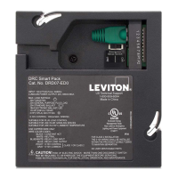
The Leviton DRC™ Controller and Smart Pack (Cat. Nos. DRC07-ED0, DRC07-E30) is a versatile device that integrates the functionalities of a DRC Controller and a Load controlling Smart Pack into a single unit. This device is designed to manage architectural controls and energy management logic within a room, offering a comprehensive solution for lighting and power control.

Function Description:

The DRC Controller and Smart Pack serves as the central hub for managing various devices within a room. It is responsible for executing all architectural control and energy management business logic. The device can be fully set up and configured using a Wi-Fi® enabled cell phone or tablet, providing a convenient and intuitive user experience.

The device supports a LumaCAN™ network, which can extend across multiple rooms and connect multiple DRC devices. This allows for scalable and integrated control solutions across larger spaces. Each DRC Controller can connect to a variety of other devices, including DRC smart packs, relay panels, Intellect™ fixtures (future), Lumina™ RF sensors, DALI™ devices, and other compatible devices. This broad compatibility ensures flexibility in system design and expansion.

Usage Features:

Mounting: The device is designed for easy installation. It can be mounted to the face of a 4-inch square junction box with a minimum volume of 30.3 cubic inches (4 in x 4 in x 2.125 in) using provided screws. When mounting, it's important to ensure that the conduit/cable entry clamp is positioned to avoid conflicts with the DRC nipple. Wires should be dressed to provide sufficient clearance. For jurisdictions requiring Class 2 network wiring in conduit, a 4-inch square extension ring and a blank cover can be added, sandwiching the smart pack between two junction boxes for Class 2 and Class 1 wiring. In jurisdictions requiring metal enclosures, appropriate enclosures should be provided or requested from Leviton. An alternative installation method involves mounting the product using the nipple through a junction box knock-out, ensuring all indicators remain visible and accessible.

Wiring: Line voltage and control wiring should be connected according to the wiring diagram. If 0-10V control wiring is run as Class 2, wires must be sleeved with suitable insulating material from the Smart Pack until they exit the junction box.

LumaCAN Connection: The device features two LumaCAN ports to maintain the required Daisy-Chain topology of the LumaCAN network. CAT6 cable with standard RJ45 connectors should be used. If two connections are needed, the terminator should be removed from one RJ45 port; if only one connection is required, the supplied terminator should remain connected. Wiring must adhere to the TIA-568B standard. The sequence of network nodes, as described in construction documents, may be critical for power distribution. All LumaCAN cable segments must be tested and validated before powering up the system. The last device in each LumaCAN run must be terminated using an RJ45 terminator plug. Each Smart Pack comes with a pre-installed terminator plug. LumaCAN connections must be wired as Class 2, following local jurisdictional requirements. If conduit is required for Class 2 wiring, a 4-inch square extension ring and blank plate should be used on the LumaCAN side of the Smart Pack, with conduit terminated to the extension ring.

Emergency Operation: The DRC Smart Pack can function as a UL 924 emergency bypass device, ensuring the relay closes during a power failure. The device offers two options for sensing power to determine an "emergency" state:

  1. Sense is Line Power through the Black wire: Upon loss of supplying power to the device, the relay will close.
  2. Sense is power over LumaCAN: Upon loss of +24V power on the LumaCAN cable, the relay will close. An "Emergency Circuits" label should be placed on the DRC Smart Pack for user awareness.

The device supports both "Can Mode" and "Line Mode" for emergency sensing. In Can Mode, the Smart Pack closes the relay and forces 0-10V to MAX brightness upon loss of +24VDC LumaCAN power or LINE power. In Line Mode, the Smart Pack closes the relay and forces 0-10V to MAX brightness upon loss of LINE power.

Configuration: The DRC is configured using an iOS or Android Wi-Fi capable device with the Leviton GreenMax DRC app. Users connect to the DRC Controller as a Wi-Fi access point (default name: GreenMax DRC-[serial number], default security: WEP, password: leviton0000) and use the app to navigate the configuration process. If the wireless access point or password changes, the network configuration can be reset by pressing and holding the Wi-Fi button for 20 seconds until the Wi-Fi LED flashes green rapidly, then releasing it. The LED will continue to flash rapidly until the reset cycle is complete, then go dark and blink slowly, indicating readiness for connection with factory default credentials. Site administrator access is required for app configuration.

Maintenance Features:

Troubleshooting:

  • Lights ON after power outage: This is normal operation. The smart pack's fail-safe feature forces the relay to close and 0-10V to full output upon power loss. After 7-10 seconds of power restoration, the device returns to its previous state and monitors the LumaCAN network.
  • Device does not operate immediately after power ON: This is normal operation. The device has a 7-10 second startup time.
  • Lights flickering: Check for bad lamp/socket connections or unsecured intermediate wires.
  • Lights did not turn ON: Check for tripped circuit breaker/blown fuse, burnt out bulbs/tubes, or unwired fixture Hot/Neutral connections.
  • Heartbeat LED is RED or WHITE: This indicates a processor or application failure. Try power cycling the DRC Smart Pack.

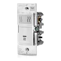
Indicator Lights and Switches: The device includes several indicator lights and switches for normal operation, providing visual feedback on its status and allowing for basic interactions.

  • Wi-Fi Switch Actions:
    • Press/Release (<1 second) or power cycle: Re-triggers SSID broadcast (times out after 15 minutes).
    • 10-second press: Enables/disables Wi-Fi (2 rapid flashes).
    • 20-second press: Resets Wi-Fi network configuration to factory default (rapid continuous flashing, reset triggered on release).
    • 25-second press: LED goes dark (no action).

  • LuminaRF/Intellect/Zigbee Switch Actions:
    • Press/Release (<1 second): Status indication (one blink for not configured, three blinks for network formed).
    • 10-second press: Enables/disables (2 rapid flashes).
    • 20-second press: Resets device to factory default (rapid continuous flashing, reset triggered on release).
    • 25-second press: LED goes dark (no action).

  • Wi-Fi Indicator:
    • Solid GREEN: Wi-Fi enabled, no traffic.
    • Blink GREEN: Network traffic.
    • OFF: Wi-Fi disabled.
  • LuminaRF/Intellect/Zigbee Indicator:
    • Solid GREEN: Enabled, no traffic.
    • Blink GREEN: Network traffic.
    • OFF: Disabled.
  • LumaCAN Indicator:
    • Solid GREEN: LumaCAN enabled.
    • Blink GREEN: Traffic.
    • OFF: LumaCAN disabled.
  • Heartbeat Indicator:
    • Solid Red: Failed application or processor failure. Possible causes/resolution: Cycle power. If not restored, remove LumaCAN cables and cycle power again.
    • Blinking Red: Duplicate LumaCAN address. Possible causes/resolution: Log into controller with app and change LumaCAN address to a unique address.
    • Solid White: Processor in reset or startup failure. Possible causes/resolution: Cycle power. If not restored, remove LumaCAN cables and cycle power again.
    • Off: Failure. Possible causes/resolution: Remove LumaCAN cables. If device starts up, there's overcurrent or short. If not, check control Power Input.

Emergency Self-Test: NFPA 101 Life Safety Code and NEC (Article 700.3 (B)) require regular testing of emergency equipment. To perform a test, interrupt normal power to the device using the EM control breaker or the device providing power to the LumaCAN network. Alternatively, a standard toggle switch on the normal power line can be used, provided it is local to the controlled load and permitted by local authorities.

Leviton GreenMax DRC DRC07-ED0 Specifications

General IconGeneral
CategoryController
ManufacturerLeviton
Product LineGreenMax
ModelDRC07-ED0
SeriesDRC
Input Voltage120-277 VAC
Frequency50/60 Hz
EnclosureNEMA 1
Control Method0-10V Dimming
CertificationsUL, cUL

Related product manuals