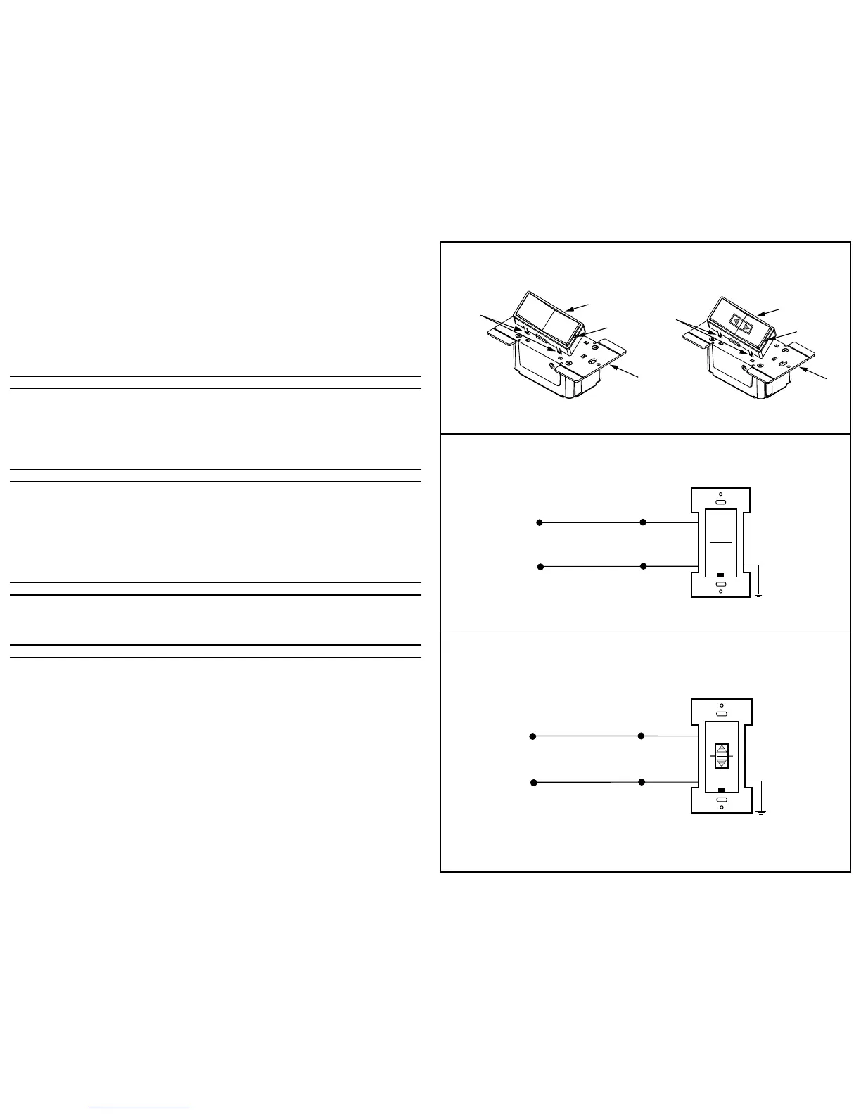
3. Connect wires per appropriate WIRING DIAGRAM as follows: BLACK (Hot) wire to BLACK lead of device, and WHITE (Neutral) to
White lead of device. Twist strands of each lead tightly together and, with circuit conductor, push firmly into appropriate wire
connector. Screw connector on clockwise making sure that no bare wire shows below the connector. Secure each wire connector
with electrical tape.
4. Remove Front Face of Cat. No. HXCxx (refer to Color Conversion Procedure) to access Control Wheels.
5. Using a small screwdriver (included), set the Number Code and Letter Code dials to the desired address by gently turning the
indicators to the proper positions (refer to Figure 3 and the examples in the Testing section).
NOTE: The HXC1A is only equipped with a housecode dial (refer to Figure 3).
6. Mount Cat. No. HXCxx in wall box using the screws provided.
NOTE: If mounted ina multi-gang box, one or more of the side sections may have to be removed. Use pliers to carefully bend side
sections back and forth until they break off (refer to Figure 2).
7. Replace Front Face (refer Color Conversion Procedure).
8. Mount wallplate.
9. Restore power at circuit breaker or fuse. INSTALLATION IS COMPLETE.
COLOR CONVERSION PROCEDURE
The color of this device can be changed to suit your interior design requirements. Simply obtain a color conversion kit of the
appropriate color from your Leviton distributor and proceed as follows (please note that the wallplate must be removed).
1. Select the color of the face you desire.
2. The frame has snaps on its sides. Using a small screwdriver, gently remove the frame from the strap (refer Figure 4).
3. Take the new frame and position it properly to the strap. Line up the plastic snaps with the square holes in the strap. Insert the
snaps on one side of the frame into the strap.
4. Firmly press sideways and down to slip the other snaps into place. The frame snaps in with a audible click. Ensure that all four
snaps are secure. Replace Decora
®
wallplate. The color conversion is complete.
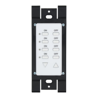
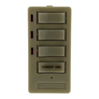
TO OPERATE (Cat. Nos. HXC1
Ø
, HXC1A and HXC1D)
Pressing the upper half of the large rocker will transmit ON and ALL ON commands (Cat Nos. HXC1
Ø
, HXC1A and HXC1D).
Pressing the bottom half of the large rocker will transmit OFF and ALL OFF commands (Cat Nos. HXC1
Ø
, HXC1A and
HXC1D). Pressing the upper half of the small rocker will transmit the BRIGHT command (Cat No. HXC1D). Pressing the bottom
half of the small rocker will transmit the DIM command (Cat No. HXC1D).
When transmitting an ON/ALL ON command, the LED will blink while the signal is being transmitted and will stay ON when the
signal has completed the transmission. When transmitting an OFF/ALL OFF command, the LED will blink while the signal is being
transmitted and turn OFF when the signal has completed the transmission. If there is a BRIGHT/DIM function on the keypad,
pressing the BRIGHT or DIM button will cause the LED on the face of the keypad to flash and will remain flashing until the button is
released.
NOTE: When used with a 2-Way Receivers, the LED's will indicate the status of those devices (i.e., if the Dimmer is turned ON at
it's source, the ON/OFF LED on the Transmitter will turn ON).
TESTING
Press the keypad to confirm that the load or loads are turned ON and OFF within two seconds of signal transmission. If the
Cat. No. HXCxx Controller appears to be functioning improperly or operates erratically, read the following paragraphs, then refer to
the Perfect Performance Checklist.
An ALL ON/OFF (Cat. No. HXC1A) controls all DHC modules set to the same letter code as on the Cat. No. HXCxx Controller. ALL
ON ONLY turns ON lighting modules. ALL OFF turns OFF ALL modules set to the same letter code.
PERFECT PERFORMANCE CHECKLIST
If the Cat. No. HXCxx Controller appears to be functioning improperly proceed with the following steps:
1. Confirm that the Controller is wired exactly as shown in the wiring diagram.
2. Confirm that the receiver module is being supplied from a 120V, 60Hz AC source ONLY.
3. Confirm that the load being controlled is in proper working order. Local switch, ON (check for burned-out bulbs, etc.).
4. Confirm that the Controller is powered and is set to transmit commands to the same letter and number code on receiver modules.
5. Confirm that the Cat. No. HXCxx keypad is installed properly.
NOTE: If the Controller still does not operate properly after following steps 1-5, proceed with diagnostic steps 6 and 7.
6. Set the Controller to transmit address P1. Using a Cat No. 6386 Signal Strength Indicator plugged in on the same branch circuit
as the Controller, confirm that the Controller is transmitting a minimum reading of 2 volts of command signal at the HI-RANGE
setting. If the signal strength is less than 2 volts, have the Controller checked.
7. Check for adequate command signal at the Cat. No. HXCxx location as follows:
A. Plug the Cat. No. 6385 Signal Test Transmitter into a receptacle on the same circuit as the Controller.
B. Using the Cat. No. 6386 Signal Strength Indicator at the HXCxx location, check the command signal amplitude. Signal
strength must be 100mV minimum. If there is less than 100mV of signal present, it may be necessary to couple both legs of
the 120/240 Volt power service at the entrance panel using a Leviton Repeater/Coupler.
C. If the Yellow ERROR CONDITION indicator is lit, there is electrical “noise” present on the AC line which is interfering with
proper module operation. The source of the noise must be identified and either filtered out or eliminated (See Technical
Manual).
8. Installation of a Coupler/Repeater is recommended in all DHC installations for maximum signal.
9. The Leviton Technical Manual covers common DHC problems and system issues in more detail.
 Loading...