WARNINGS AND CAUTIONS
• TO AVOID FIRE, SHOCK, OR DEATH: TURN OFF POWER at circuit breaker or fuse and test that power is off before wiring!
• To be installed and/or used in accordance with electrical codes and regulations.
• Confirm that device ratings are suitable for application prior to installation.
• Use this device with copper or copper clad wire only.
• Connect to field wiring rated for 60° C or greater.
• DO NOT install if product appears to be damaged.
• For indoor use only.
• Read these instructions before installation and retain for future reference.
DI-000-TS300-05A
INSTALLATION INSTRUCTIONS ENGLISH
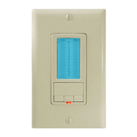
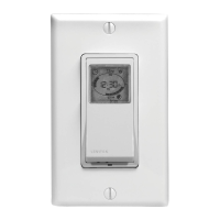
Digital Programmable Wall Box Timer
Cat. No. TS300 - 120-277VAC, 50/60Hz
WIRING FOR TS300 SERIES
1. WARNING: TO AVOID FIRE, SHOCK, OR DEATH: TURN OFF POWER at circuit
breaker or fuse and test that power is off before wiring!
2.
Connect the timer black wire to line. Connect the timer red wire to the load. Cap
unused yellow wire.
3.
Connect the green wire to the ground. Unit must be properly grounded to operate.
4. Mount the timer inside electrical box using 2 mounting screws provided.
5. Turn power ON at the electrical panel.
6. Timer dip switches are factory preset for 2 hour operation. Change dip switches and
program only if custom setting is desired. Follow SET-UP INSTRUCTIONS.
7.
Close timer cover and install wall plate. Settings are now tamper resistant.
NOTE: Wall plate must be removed to open timer cover and change settings.
Red
Black
Yellow
Load
Green
Ground
RETROFITTING A TS300 TO EXISTING 3-WAY OR 4-WAY SWITCH
1. WARNING: TO AVOID FIRE, SHOCK, OR DEATH: TURN OFF POWER at circuit breaker or fuse and test that power is off before wiring!
2.
Disconnect the second 3-way switch.
3. Connect the timer red wire to the load. Connect the timer black wire to "Traveler A" and the timer yellow wire to "Traveler B. Connect the green wire to the ground. Unit must be
properly grounded to operate.
4.
Mount the timer inside electrical box using two mounting screws provided.
5a. (3-way switch wiring Figure 2): At switch #1 connect a wire between the Hot leg of the 3-way and "Traveler A" inside of that switch's gang-box.
5b.
(4-way switch wiring Figure 3): Replace wall switches with a properly rated momentary switch. At switch #1, connect "Traveler A" to Hot leg and one side of momentary switch.
Connect "Traveler B" to other side of momentary switch. At switch #2, connect "Traveler A" together and to one side of momentary switch. Connect "Traveler B" together and to other
side of momentary switch.
6.
Turn power ON at the electrical panel.
7. Timer dip switches are factory preset for 2 hour operation. Change dip switches and program only if custom setting is desired. Follow SET-UP INSTRUCTIONS.
8. Close timer cover and install wall plate. Settings are now tamper resistant.
NOTE: Wall plate must be removed to open timer cover and change settings.
NOTE: Maximum wire length from the 3-way (multi-way) switch to timer is 100 ft.
Red
BlackTraveler A
Connect a wire inside box
between Traveler A and Hot
YellowTraveler B
Load
Green
Ground
SET FOR 4-WAY OPERATION
The TS300 timers are factory preset for 3-way wiring with a maintained wall switch. Optional 4-way (multi-way): Open timer door and press reset button. Unit will display 3-W representing
3-way. Press the TIMER button to change screen to 4-W. After 10 seconds the display will blink twice. Display will confirm operating hertz (60 typical). Unit is now ready to program.
Momentary switches must be used as additional switch positions in the 4-way (multi-way) setting. Refer to wiring diagrams.
Red
Black
BlackTraveler ATraveler A
Connect a wire inside box
to join Traveler A to switch
Connect a wire inside box
to join Traveler B to switch
Use momentary switches at all additional locations
Connect Traveler A
to Hot
Switch #1 Switch #2
YellowTraveler BTraveler B
Green
Ground
Load
Figure 1
Figure 2
Figure 3