Single Pole (One location) or 3-Way (Multi-location)
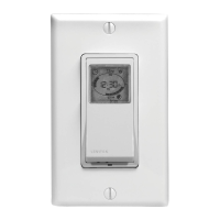
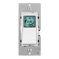
Digital Timer Switch
Cat. No. VPT24-1P, Lighted
Incandescent-1800W – Resistive/Inductive-15A – Motor-1 HP
120VAC, 60Hz
INSTALLATION INSTRUCTIONS
WARNINGS AND CAUTIONS
:
• Tobeinstalledand/orusedinaccordancewithappropriateelectricalcodesandregulations.
• Ifyouareunsureaboutanypartoftheseinstructions,consultanelectrician.
• vizia+™electronicswitchesarenotcompatiblewithstandard3-wayor4-wayswitches.Theymustbeusedwithcompatiblevizia+™on/offremotes.
• Recommendedminimumwallboxdepthis2-1/2".
WARNINGS AND CAUTIONS
:
•Useonlyone(1)vizia+
TM
digitaltimerswitchinamulti-locationcircuitwithupto9coordinatingremoteswitches(withoutLEDs)orupto4matchingremoteswitches(withLEDs)
.
• Maximumwirelengthfromdigitaltimerswitchtoallinstalledremotescannotexceed300ft(90m).
• Disconnectpoweratcircuitbreakerorfusewhenservicing,installingorremovingxture.
• Usethisdevicewithcopper or copper clad wire only.
IMPORTANT :For3-Wayapplications,notethatoneofthescrew
terminalsfromtheoldswitchbeingremovedwillusuallybeadifferent
color(Black)orlabeledCommon.Tagthatwirewithelectricaltapeand
identifyasthecommon(LineorLoad)inboththeswitchwallboxand
remotewallbox.
DI-000-VPT24-02B
Tools needed to install your Timer Switch
Slotted/PhillipsScrewdriver ElectricalTape Pliers
Pencil Cutters Ruler
Hot (Black)
Neutral (White)
Load
Timer Switch
BKWH
Black
White
RD
Green
Ground
YL/RD
Line
120VAC, 60Hz
Use lead for 3-Way or more
applications only. For single
pole applications, do not
remove the insulating label.
WIRING TIMER SWITCH:
Connect wires per WIRING DIAGRAM as follows:
• GreenorbarecopperwireinwallboxtotimerswitchGreenlead.
• LineHotwallboxwiretotimerswitchBlacklead.
• LoadwallboxwiretotimerswitchRedlead.
• LineNeutralwallboxwiretotimerswitchWhitelead.
• NOTE:Iflabelismissingplaceelectricaltapearoundthetimerswitch
Yellow/Redlead.Ensurenostrandsareexposed.
• Proceed to Step 5.
Hot (Black)
Neutral (White)
Coordinating Remote Switch (no LED)
YL/RD
YL/RD
RD
WH
RD
BK
Black
BKWH
White
Line
120VAC, 60Hz
Green
Ground
Green
Ground
(unused)
(unused)
Load
Timer Switch
WIRING TIMER SWITCH:
Connect wires per WIRING DIAGRAM as follows:
NOTE:ThetimerswitchmustbeinstalledinawallboxthathasaLineHot
connection.
NOTE:Maximumwirelengthfromtimerswitchtoallinstalledremotes
cannotexceed300ft(90m).
• GreenorbarecopperwireinwallboxtotimerswitchGreenlead.
• LineHot(common)wallboxwireidentied(tagged)whenremovingold
switchtotimerswitchBlacklead.
• FirstTravelerwallboxwiretotimerswitchRedlead
(note wire color).
• RemoveRedinsulatinglabelfromtimerswitchYellow/Redlead.
• SecondTravelerwallboxwiretotheYellow/Redlead(note wire color).
Thistravelerfromthetimerswitchmustgototheterminalscrewonthe
remotemarked"YL/RD".
• LineNeutralwallboxwiretotimerswitchWhitelead.
WIRING COORDINATING REMOTE SWITCH (VP0SR-10):
Connect wires per WIRING DIAGRAM as follows:
NOTE:"BK"and"RD"terminalsoncoordinatingremoteswitchare
unused.Tightenbothscrews.
NOTE:Maximumwirelengthfromtimerswitchtolastremotecannot
exceed300ft(90m).
• GreenorbarecopperwireinwallboxtoGreenterminalscrew.
• Loadwallboxwireidentied(tagged)whenremovingoldswitchtoFirst
Traveler (note color as above).
• SecondTravelerwallboxwire(note color as above)toterminalscrew
marked"YL/RD".ThistravelerfromtheremotemustgototheYellow/
Redleadonthetimerswitch.
• RemoveWhiteinsulatinglabelfromterminalscrewmarked"WH".
• LineNeutralwallboxwiretoterminalscrewmarked"WH".
• ProceedtoStep5.
Installing your Timer Switch
NOTE:UsecheckboxeswhenStepsarecompleted.
WARNING:
TO AVOID FIRE SHOCK OR DEATH; TURN
OFF POWER atcircuitbreakerorfuseandtestthatpoweris
offbeforewiring!
ONOFF
ONOFF
ONOFF
ONOFF
ONOFF
ONOFF
ONOFFONOFF
ONOFF
ONOFF
ONOFF
ONOFF
Step 1
Identifying your wiring application (most common):
NOTE:Ifthewiringinyourwallboxdoesnotresembleanyof
thesecongurations,consultaqualiedelectrician.
2
4
3
1
2
4
1
5
3
Single Pole
1. Line (Hot)
2. Neutral
3.Ground
4. Load
3-Way
1. Line or Load
(see important instruction below)
2. Neutral
3. Ground
4. First Traveler – note color
5. Second Traveler – note color.
NOTE:Formatchingremote
w/LEDsinstallation,theFirst
TravelerbecomesLineHot.
Step 2
Green
Yellow/Red
Insulating label:
This wire is used in 3-way installations only.
For single pole installations, do not remove insulating label.
Red
White
Black
1
2
4
3
Single Pole Wiring Application:
Step 4a
2
1
4
BK
RD
YL/RD
Coordinating Remote Switch Timer Switch
5
3
Terminal
Screw marked
White (WH)
Green
Yellow/
Red
Red
White
Black
Terminal
Screw marked
Yellow/Red
(YL/RD)
2
5
1
3
4
WH
3-Way Wiring with Coordinating Remote Switch,
VP0SR-10, (no LED) Application:
Step 4b
• Makesurethattheendsofthewiresfromthewallboxare
straight (cut if necessary).
• Removeinsulationfromeachwireinthewallboxasshown.
• ForSingle-PoleApplication,gotoStep4a.
• For3-WayCoordinatingRemote(noLEDs)Application,gotoStep4b.
• For3-WayMatchingRemote(withLEDs)Application,gotoStep4c.
Cut
(if necessary)
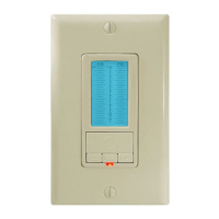
Changing the color of your device:
Yourdevicemayincludecoloroptions.Tochangecoloroftheface,
proceedasfollows:
12
PM
A
T
h
MEN
U
SET
12
AM
12
P
M
A
Th
MENU
SET
12
AM
Push in side
at tab to release
Line up tabs and
press in sides one at
a time to attach
5/8"
(1.6 cm)
Strip Gage
(measure bare
wire here)
Step 3
Preparing and connecting wires:
Pulloffpre-cutinsulationfromtimerleads.Makesurethat
theendsofthewiresfromthewallboxarestraight(cut if
necessary).Removeinsulationfromeachwireinthewall
boxasshown.
WIRE NUT / # OF CONDUCTOR
COMBINATION CHART
1-#12w/1to3#14,#16or#18
2-#12w/1or2#16or#18
1-#14w/1to4#16or#18
2-#14w/1to3#16or#18
For non-standard wiring applications, refer
to Wire Nut and Conductor Size Chart
3-Way Wiring with Matching Remote Switch,
VP0SR-1L, (w/LED) Application:
Step 4c
BK
RD
YL/RD
Matching Remote Switch Timer Switch
3
5
1
2
4
Green
Yellow/
Red
Red
White
Black
2
5
1
3
4
Additonal Neutral Wire
WH
NOTE:ThetimerswitchmustbeinstalledinawallboxthathasaLoad
connection.Thematchingremotemustbeinstalledinawallboxwith
aLineHotconnectionandaNeutralconnection.ANeutralwiretothe
matchingremoteneedstobeaddedasshown.
Ifyouareunsureaboutanypartoftheseinstructions,consultan
electrician.
NOTE:Maximumwirelengthfromdimmertoallinstalledremotescannot
exceed300ft(90m).
WIRING MATCHING REMOTE SWITCH, VP0SR-1L
(wall box with Line Hot connection):
Connect wires per WIRING DIAGRAM as follows:
• GreenorbarecopperwireinwallboxtoGreenterminalscrew.
• LineHot(common)wallboxwireidentied(tagged)whenremoving
oldswitchandFirstTravelertoremoteterminalscrewmarked"BK".
• SecondTravelerwallboxwirefromswitchtoremoteterminalscrew
marked"YL/RD"(note wire color).Thistravelerfromtheremotemust
gototheYellow/Redleadonthetimerswitch.
• LineNeutralwallboxwiretoremoteterminalscrewmarked"WH".
WIRING TIMER SWITCH (wall box with Load connection):
Connect wires per WIRING DIAGRAM as follows:
• GreenorbarecopperwireinwallboxtotimerswitchGreenlead.
• Loadwallboxwireidentied(tagged)whenremovingoldswitchtotimer
switchRedlead.
• FirstTravelerLineHottotimerswitchBlacklead.
• RemoveRedinsulatinglabelfromYellow/Redlead.
• SecondTravelerwallboxwire(note color as above)totimerswitch
Yellow/Redlead.Thistravelerfromtheswitchmustgototheterminal
screwontheremotemarked"YL/RD".
• LineNeutralwallboxwiretotimerswitchWhitelead.
• ProceedtoStep5.
Hot (Black)
Neutral (White)
Timer Switch
Black
White
Line
120VAC, 60Hz
Load
Green
Ground
Green
Ground
Matching Remote Switch (w/LED)
YL/RD
RD YL/RD
WH
BK
BK
WH
• Positionallwirestoprovide
roominoutletwallboxfor
device.
• Ensurethattheword“TOP”is
facingupondevicestrap.
• Partiallyscrewinmounting
screwsinwallboxmounting
holes.
Testing your Switch prior to mounting in
wall box:
Step 5
NOTE:Dresswireswithabendasshown
indiagraminordertorelievestresswhen
mountingdevice.
• Restorepoweratcircuitbreakerorfuse.
• Waituntilortimeisdisplayedon
the screen.
• PresspaduntillocatorlightisOFF.Load
should turn ON.
If loads do not turn ON, refer to the
TROUBLESHOOTING section.
Switch Mounting:
TURN OFF POWER AT CIRCUIT BREAKER OR FUSE.
• Installationmaynowbecompleted
bytighteningmountingscrewsinto
wallbox.Attachwallplate.
Step 6
Restore Power:
Restorepoweratcircuitbreakerorfuse.
Installation is complete.
NOTE: TheDigitalTimerSwitchisequippedwithaninternal
rechargeablebatteryback-uptokeepprogrammedsettings
intheeventofapowerinterruption.
Step 7
http://waterheatertimer.org/Leviton-timers-and-manuals.html