User Manual for BFS-i06
www.levitronix.com
PL-3502-00, Rev04, DCO# 24-054
This document and its content is confidential and the property of Levitronix
®
and shall not be reproduced, distributed,
disclosed or used for manufacturing or sale of Levitronix
®
products without the expressed written consent of Levitronix
®
.
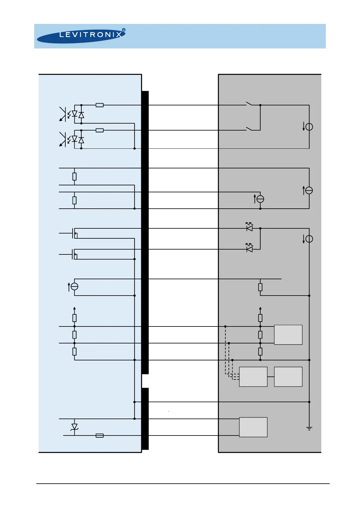
4.1.2 Electrical Schematics Overview of Motor Interface
Figure 14: Electrical schematics of motor interface
Note 1: RS485 to USB converter cable with termination resistors to be ordered according to Table 2
Note 2: Do not use multiple master devices on the RS485 at the same time
Bearingless fan
interface circuit
Example of user
interface circuit
240 W
240 W
2.2 kW
A2 / Brown:
Digital output 1
A3 / White:
Digital output 2
B3 / Yellow:
Digital input ground
B5 / Gray:
Digital input 2
B4 / Pink:
Digital input 1
B2 / Blue:
Analog input ground
B6 / Violet:
Analog input 1
B1 / Gray-pink:
Analog input 2
A4 / White-green:
Ground (GND)
A1 / Blue-red:
Analog output
A5 / Brown-green:
RS485+
A6 / White-yellow:
RS485-
3 / Yellow-green:
Cable Shield
GND
4..20 mA
4...20 mA
Personal
Computer
(Service)
5..24 V
200 mA
5..24 V
4..20 mA
Analog inputs not galvanically isolated
Max. pin voltage to GND = 10 V
Pin numbers, wire colors
and wire name
510 W
1 / Red:
48 VDC
2 / Black:
Ground/Earth
120 W
3.3..5 V
56 V
10 A
Analog output not galvanically isolated
Digital outputs not galvanically isolated
2.2 kW
PLC connector
450 W
Tool
Control
510 W
RS485 - USB
Converter
with
Termination
3.3 V
Power connector
AC/DC
Supply
48 VDC
 Loading...