User Manual for BFS-i06
www.levitronix.com
PL-3502-00, Rev04, DCO# 24-054
This document and its content is confidential and the property of Levitronix
®
and shall not be reproduced, distributed,
disclosed or used for manufacturing or sale of Levitronix
®
products without the expressed written consent of Levitronix
®
.
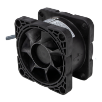
Bearingless Fan
(ATEX / IECEx)
BFS-i06.1 (5 m)
BFS-i06.1-22 (2.2 m)
48 V DC ±10%, 240 W
(Option: 24 V DC ±5%, 65 W, with reduced max. speed of 8000 rpm)
915 Pa (3.68 inH
2
O), 500 m
3
/h (294 cfm)
850 Pa, 440 m
3
/h, 13000 rpm
(Optional 24 V supply voltage: 320 Pa, 260 m
3
/h, 8000 rpm)
II 2D Ex h mb IIIC T85 °C Db
Ambient and gas temperature range 0 to 40 °C
PLC with 2 analog inputs 4-20 mA
1 analog output 4-20 mA
2 digital inputs 0-24 V (optocoupler)
2 digital outputs 0-24 V / 100 mA (open drain)
RS485 interface, Modbus protocol (extended control or service through
fieldbus or Levitronix
®
Service Software)
Flange on both motor sides with mounting holes 4 x Ø 12 mm on
diameter 138 mm. Flange inside Ø 100 mm, outside 120 mm x 120 mm
5/2.2 m + 0.2/0.8 m wires with TE connectors for power and PLC signals
Polypropylene, electrically conductive, flame retardant
Cable: PVC jacket, PVDF bushing
1.4 kg, 3.1 lb (for 5 m version)
Table 1: Specification of standard configuration
Set of ICP-5.1-03
and ICS-5.1-03
ICP-5.1-03 (0.3 m)
ICP-5.1-15 (1.5 m)
PVC insulated open wires (3 x 1.5 mm
2
) with TE connector
Connection of fan cable to DC power supply
ICS-5.1-03 (0.3m)
ICS-5.1-15 (1.5 m)
PVC insulated open wires (12 x 0.14 mm
2
) with TE connector
Connection of fan cable to PLC signals and RS485 fieldbus
Certification / Standards
DIN-rail mountable PCB with connectors for:
- 4 x Signal for BFS-i06 fans (TE Connectivity 1-1827875-6)
- 4 x Power for BFS-i06 fans (TE Connectivity 1-178136-3)
- 1 x Power supply connector (Wago 2624-3105)
- 22 x PLC push-in (analog/digital inputs/outputs, RS485)
- 1 x Circular COM for LUI-B.1 or USB-RS485 adaptor
Easy wiring of power and PLC signals for up to four BFS-i06 fans, see
section 4.3 for further information
Firmware A8.00, IP65, 5 to 24 V supply voltage
Control of fan via handheld device with display and menu buttons.
USB connector (A) with termination resistor and cable (2 m) with
connector pair (B and C) for external RS485 wire connection.
Magnetically isolated. Included is a USB space saver cable (D)
Control or service of fan via USB port of a PC with Levitronix® Service
Software
IP Adaptor Cable
Signal 6 Wires
ICS-1.1-10 (1 m)
ICS-1.1-30 (3 m)
PVC jacket, connectors: circular to circular type
Connection of user panel (LUI-B.1) to interface panel (FIP-2.1)
IP Adaptor Cable
Signal 6 Wires
ICS-1.2-10 (1 m)
ICS-1.2-50 (5 m)
PVC jacket, connectors: circular type to screw type
Connection of user panel (LUI-B.1) to adaptor cable (ICS-5.1) and 5 to
24 V supply
IP Adaptor Cable
Signal 6 Wires
PVC jacket, connectors: circular type to screw type
Connection of interface panel (FIP-2.1) to USB adaptor (YN-485I-TR)
ATEX Cable
Sealing System
Sleeve (A) and Gasket (B): Stainless Steel, EPDM
Frame(C) and 2x Cable Module (D): Roxylon (EPDM Rubber)
Lubricant (E) and measurement plates (F) are included
Table 2: Specification of standard accessories
Note 1: See section 3.1.2 for a list of tested power supplies for one or multiple fans
 Loading...