This document and its content is confidential and the property of Levitronix
®
and shall not be reproduced, distributed,
disclosed or used for manufacturing or sale of Levitronix
®
products without the expressed written consent of Levitronix
®
.
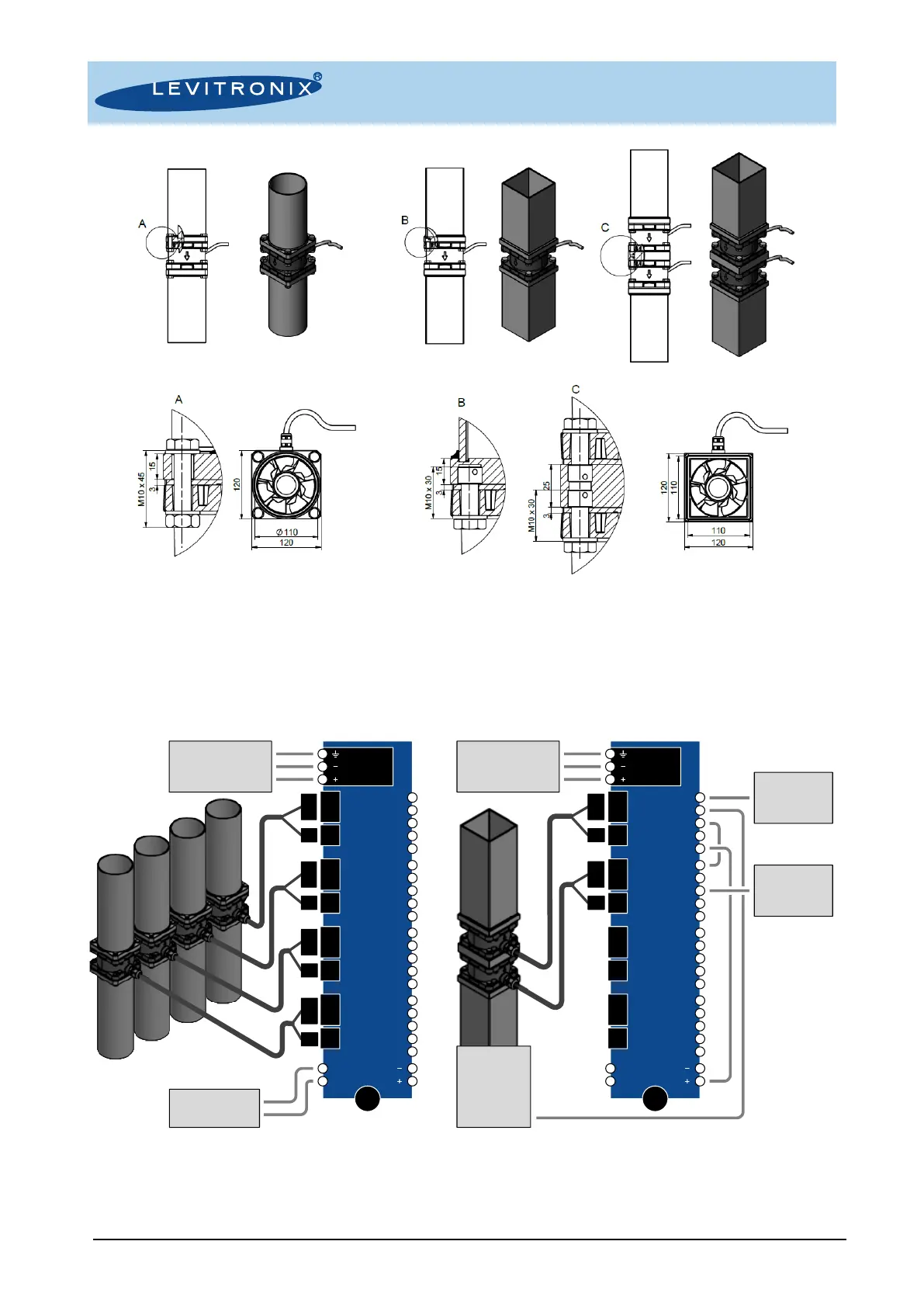
Figure 17: Examples of mounting with and through holes (left) self-cutting thread inserts (right)
4.3 Installation Examples with Interface Panel
The interface panel FIP-2.1 can be used for easy wiring of up to four fans. The panel can be mounted to a DIN
rail. Figure 18 describes two of many possible scenarios. For more in-depth information contact Levitronix
®
technical support (chapter 6.3). See section 3.1.2 for the selection of the power supply.
Figure 18: Examples of fan installation with interface panel FIP-2.1
Left: Four fans are connected to a single power supply and controlled individually through fieldbus interface
Right: Two fans are mounted in series and controlled through PLC. The first fan runs in process mode using the feedback from a
pressure or flow sensor, the second fan is configured to match the speed of the first one. They act as one process control unit with
higher pressure performance (the same configuration may be used with fans mounted in parallel to achieve higher flow performance)
 Loading...