This document and its content is confidential and the property of Levitronix
®
and shall not be reproduced, distributed,
disclosed or used for manufacturing or sale of Levitronix
®
products without the expressed written consent of Levitronix
®
.
2.5 Pressure-Flow Curves
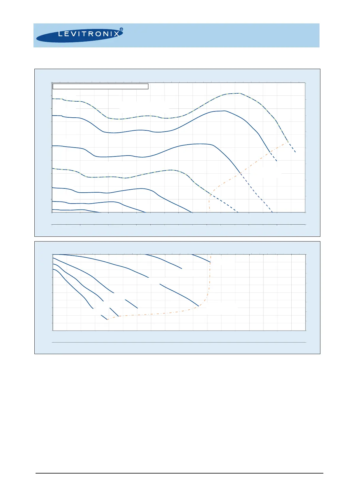
Figure 9: Pressure-flow curves of bearingless fan BFS-i06.1
Note: Typical values measured for BFS-i06.1
• Pressure Drop Coefficient at 0 rpm: C = 0.0075 (P = C x Q
2
, Q = Flow [m
3
/h], P = Pressure Drop [Pa]).
• 48 V / 24 V Supply Voltage: The maximum rotational speed is limited to 13000 rpm for 48 V supply
voltage and 8000 rpm for 24 V supply voltage.
• Negative Rotation Direction: Negative rotational speeds can be enabled in the Levitronix
®
Service
Software or via Modbus command. This feature can be used to block an existing flow, as replacement
for actively controlled valves. If negative flow needs to be avoided for safety reasons, it is
recommended to install passive check valves or a safety shutdown mechanism to deactivate the
bearingless fan in case of negative flow.
• Serial or Parallel Operation of Multiple Fans: Multiple fans can be used to achieve higher pressure
or flow levels.
a. Serial: Pressure is multiplied by up to the number of fans, while flow remains unchanged
b. Parallel: Flow is multiplied by up to the number of fans, while pressure remains unchanged
 Loading...