Description
The oil is separated from the gas in the TRIVAC B in two
steps as described above. First, small droplets are
coalesced into large drops in the internal demister (2/11)
fitted above the exhaust valve (2/10). Then, the large
drops fall into the oil reservoir as the exhaust gas is
diverted by the inner walls of the oil case.Thus a low loss
of oil is obtained. This and the large usable oil reservoir
ensure long intervals between oil changes even at high
intake pressures.
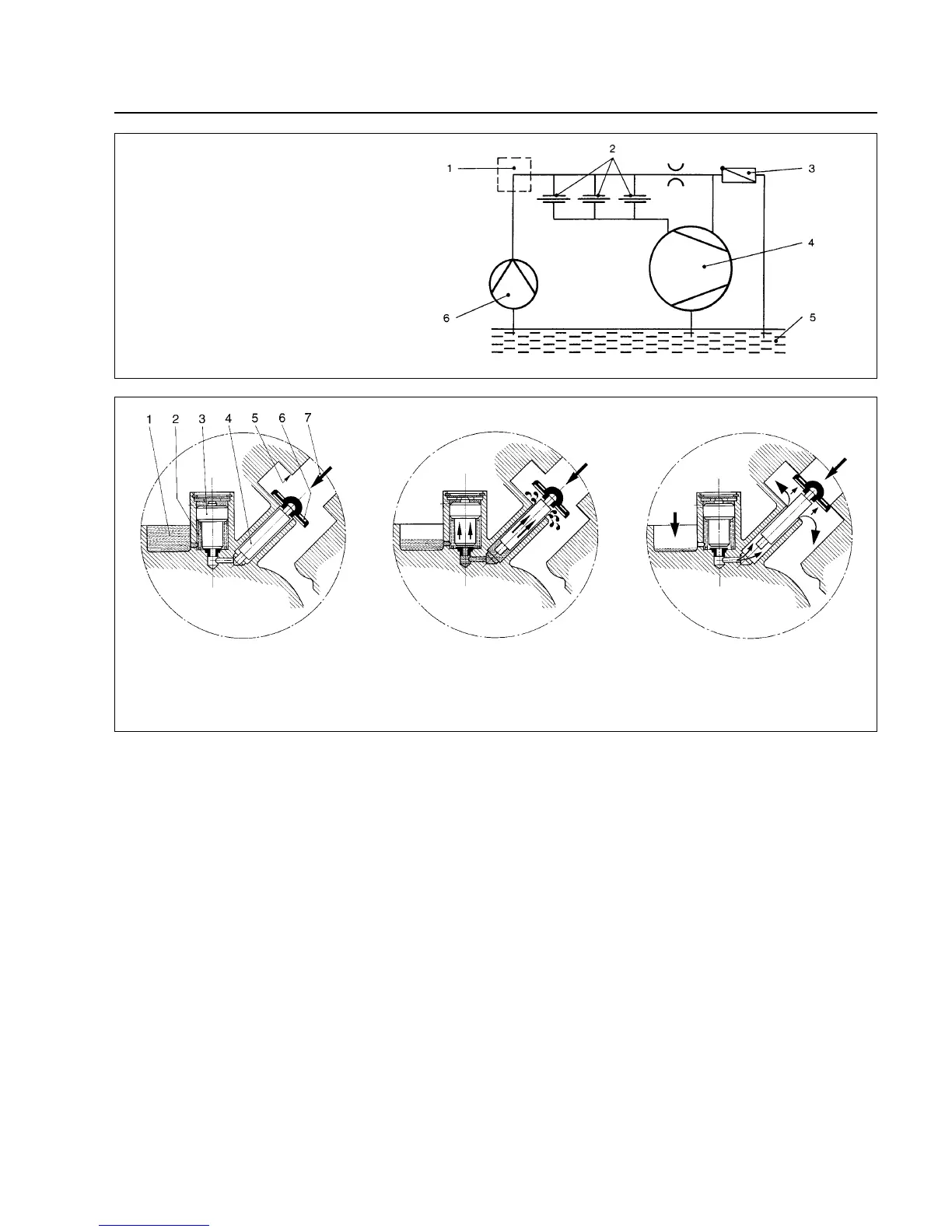
The vacuum is maintained by the TRIVAC B through an
integrated hydropneumatic anti-suckback valve (2/3)
which is controlled via the oil pressure.
During operation of the TRIVAC B the control piston (4/3)
remains sealed against a spring (4/2) by the oil pressure.
The valve disc (4/6) of the anti-suckback valve is held at
the lower position by its own weight (valve open).
When the pump stops (because it has been switched off
or because of a failure), the oil pressure drops and the
spring (4/2) presses the control piston (4/3) up. Thus a
connection is provided between the oil case or the oil
reservoir (4/1) and the piston (4/4) of the anti-suckback
5
valve. Due to the pressure difference between the oil
case and the intake port the oil presses the piston (4/4)
up and the valve plate (4/6) against the valve seat (4/5).
The quantity of oil in the oil reservoir (4/1) prevents the
entry of air into the intake port (2/1) at the beginning of
this process.
After the oil has flowed out from the reservoir and when
the valve plate rests on the valve seat, air follows in,
which vents the pump chamber and forces the valve disc
(4/6) against its seat.
This effectively prevents backstreaming of oil or oil
vapours. The anti-suckback valve (2/3) operates
independently of the operating mode of the pump, i.e.
also with gas ballast.
Fig. 3 Schematic of the lubricating system
Fig. 4 Hydropneumatic anti-suckback valve
Key to Fig. 3
1 Accessories
2 Bearings
3 Non-return valve
4 Pump chamber of the TRIVAC
5 Oil reservoir
6 Oil pump
Key to Fig. 4
1 Oil reservoir 5 Valve seat
2 Spring 6 Valve disk
3 Control piston 7 Gas inlet
4 Anti-suckback piston

 Loading...


