EasyManua.ls Logo

LG Chem EM048063P3S - User Manual

Default Icon
23 pages
Print Icon
To Next Page IconTo Next Page
Loading...
48 V Standalone Battery Module
Service Manual
Question and Answer IconNeed help?

Do you have a question about the LG Chem EM048063P3S and is the answer not in the manual?

Summary

Chapter 1 Alerts by Status Indicators

1.1 Abnormal states

Defines warning, fault 1, and fault 2 levels for module instability and failure.

1.2 Voltage abnormality

Details issues like cell overvoltage, undervoltage, and module voltage differences.

1.3 Current abnormality

Covers over-charged and over-discharged current and power conditions.

1.4 Temperature abnormality

Explains high, low, and differential temperature issues within the module.

1.5 Lost communication

Addresses communication loss between modules and with the higher level system.

1.6 State of charge

Describes alerts for low and high State of Charge (SOC) conditions.

Chapter 2 Replacements

2.1 Hot-swapping battery modules

Procedures for identifying and replacing battery modules without system shutdown.

2.2 Checking fuse

Instructions for inspecting and replacing the fuse within a battery module.

2.3 Expanding the ESS

Steps to increase the Energy Storage System capacity by adding modules.

2.4 Reducing the ESS

Steps to decrease the Energy Storage System capacity by removing modules.

Chapter 3 Formulas for Hot-Swapping

Chapter 4 Block diagram of BMS

Overview

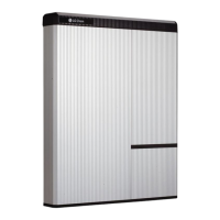
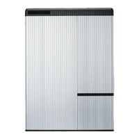
The LG Chem 48 V Standalone Battery Module is a sophisticated energy storage solution designed for various applications, with a particular focus on residential use for models like EM048063P3S2 and EM048126P3S7. This service manual provides comprehensive guidance on its operation, maintenance, and troubleshooting.

Function Description:

The battery module serves as a standalone energy storage system (ESS), capable of charging and discharging to provide power. It incorporates a Battery Management System (BMS) that monitors and controls various parameters to ensure safe and efficient operation. Key components of the BMS include:

  • Charge FET and Discharge FET: These field-effect transistors manage the flow of current during charging and discharging cycles.
  • Cell voltage sensing: Continuously monitors the voltage of individual cells within the module to detect overvoltage or undervoltage conditions.
  • Temperature sensing: Tracks the internal temperature of the battery module to prevent overheating or excessive cooling.
  • Pre-Charge circuit: Specifically designed for models like EM048063P3S2, EM048063P3S4, EM048063P3S5, EM048126P3S7, and EM048126P3S8, this circuit prevents inrush current during activation, protecting the system from sudden power surges.
  • Dry contact and Communication ports: Facilitate communication with higher-level systems and other battery modules, enabling integrated energy management.
  • Fan (optional): Provides active cooling when necessary to maintain optimal operating temperatures.

The module's front panel features status indicators that provide visual cues about its operating state, including normal operation, state of charge (SOC) levels (≥75%, ≥50%, ≥25%, <25%), voltage imbalance, warning, Fault 1, and Fault 2 states. These indicators are crucial for quick diagnosis of potential issues.

Important Technical Specifications:

While specific numerical values for all technical specifications are not explicitly detailed for all models, the manual highlights critical thresholds and operational limits:

  • Voltage:

    • Cell Overvoltage Warning: > 4.25 V for 3 seconds (Charge limit: 0%, Discharge limit: 100%, Release condition: < 4.20 V for 3 seconds).
    • Cell Overvoltage Fault 1: > 4.28 V for 3 seconds (Charge limit: 0%, Discharge limit: 100%, Release condition: < 4.25 V for 3 seconds).
    • Cell Overvoltage Fault 2: > 4.30 V for 3 seconds (Charge limit: 0%, Discharge limit: 0%).
    • Cell Undervoltage Warning: < 2.8 V for 3 seconds (Charge limit: 100%, Discharge limit: 0%, Release condition: > 3.0 V for 3 seconds).
    • Cell Undervoltage Fault 1: < 2.6 V for 3 seconds (Charge limit: 100%, Discharge limit: 0%, Release condition: > 2.8 V for 3 seconds).
    • Cell Undervoltage Fault 2: < 2.4 V for 3 seconds (Charge limit: 0%, Discharge limit: 0%). The battery module turns off 10 minutes after entering this state.
    • Too Low Module Voltage Fault 2: < 29.0 V for 3 seconds (Charge limit: 0%, Discharge limit: 0%). The battery module turns off 10 minutes after entering this state.
    • Too Large Voltage Difference Between Cells Warning: > 0.3 V for 3 seconds (Charge limit: 50%, Discharge limit: 50%, Release condition: < 0.2 V for 3 seconds).
    • Too Large Voltage Difference Between Cells Fault 1: > 0.5 V for 3 seconds (Charge limit: 0%, Discharge limit: 0%, Release condition: < 0.3 V for 3 seconds). This condition is active when the lowest cell voltage is higher than 3.5 V.
  • Current:

    • Over-charged Current Warning: > 68.8 A for 3 seconds (Charge limit: 0%, Discharge limit: 100%, Release condition: < 66.1 A for 3 seconds).
    • Over-charged Current Fault 1: > 71.4 A for 3 seconds (Charge limit: 0%, Discharge limit: 100%, Release condition: < 68.8 A for 3 seconds).
    • Over-charged Current Fault 2: > 74.1 A for 3 seconds (Charge limit: 0%, Discharge limit: 0%).
    • Over-discharged Current Warning: > 68.8 A for 3 seconds (Charge limit: 100%, Discharge limit: 0%, Release condition: < 66.1 A for 3 seconds).
    • Over-discharged Current Fault 1: > 71.4 A for 3 seconds (Charge limit: 100%, Discharge limit: 0%, Release condition: < 68.8 A for 3 seconds).
    • Over-discharged Current Fault 2: > 74.1 A for 3 seconds (Charge limit: 0%, Discharge limit: 0%).
  • Power (for residential models EM048063P3S2 and EM048126P3S7):

    • Over-charged Power Warning: > Charge power limit × 110% W for 40 seconds (Charge limit: 0%, Discharge limit: 100%, Release condition: < Charge power limit × 0% W or 155.4 W for 3 seconds).
    • Over-charged Power Fault 1: > Charge power limit × 115% W for 40 seconds (Charge limit: 0%, Discharge limit: 100%, Release condition: < Charge power limit × 0% W or 155.4 W for 3 seconds).
    • Over-charged Power Fault 2: > Charge power limit × 120% W for 40 seconds (Charge limit: 0%, Discharge limit: 0%).
    • Over-discharged Power Warning: > Discharge power limit × 110% W for 40 seconds (Charge limit: 0%, Discharge limit: 100%, Release condition: < Discharge power limit × 0% W or 155.4 W for 3 seconds).
    • Over-discharged Power Fault 1: > Discharge power limit × 115% W for 40 seconds (Charge limit: 0%, Discharge limit: 100%, Release condition: < Discharge power limit × 0% W or 155.4 W for 3 seconds).
    • Over-discharged Power Fault 2: > Discharge power limit × 120% W for 40 seconds (Charge limit: 0%, Discharge limit: 0%).
    • The discharge path is capable of withstanding 70 W with a resistance of 60 Ω.
  • Temperature:

    • Too High Battery Temperature Warning: > 50.0°C for 3 seconds (Charge limit: 50%, Discharge limit: 50%, Release condition: < 48.0°C for 3 seconds).
    • Too High Battery Temperature Fault 1: > 55.0°C for 3 seconds (Charge limit: 0%, Discharge limit: 0%, Release condition: < 50.0°C for 3 seconds).
    • Too High Battery Temperature Fault 2: > 60.0°C for 3 seconds (Charge limit: 0%, Discharge limit: 0%).
    • Too Low Battery Temperature Warning: < -12.0°C for 3 seconds (Charge limit: 50%, Discharge limit: 50%, Release condition: > -10.0°C for 3 seconds).
    • Too Low Battery Temperature Fault 1: < -15.0°C for 3 seconds (Charge limit: 0%, Discharge limit: 0%, Release condition: > -12.0°C for 3 seconds).
    • Too Low Battery Temperature Fault 2: < -20.0°C for 3 seconds (Charge limit: 0%, Discharge limit: 0%).
    • Too Large Temperature Difference Inside Battery Module Fault 1: > 10.0°C for 3603 seconds (Charge limit: 0%, Discharge limit: 0%, Release condition: < 5.0°C for 3 seconds).
  • State of Charge (SOC):

    • Too Low SOC Warning: < 2.0% for 10 seconds (Charge limit: 100%, Discharge limit: 50%, Release condition: > 3.0% for 10 seconds).
    • Too High SOC Warning: > 99.0% for 10 seconds (Charge limit: 50%, Discharge limit: 100%, Release condition: < 98.0% for 10 seconds).
  • Communication:

    • Lost Communication Between Battery Modules Fault 1: Lost communication for 10 seconds (Charge limit: 0%, Discharge limit: 0%, Release condition: Resumed for 1 second).
    • Lost Communication Between Battery Modules Fault 2: Lost communication for 50 seconds (Charge limit: 0%, Discharge limit: 0%).
    • Lost Communication with Higher Level System Fault 2: Lost communication for 610 seconds (Charge limit: 0%, Discharge limit: 0%).

Usage Features:

The battery module is designed for integration into a larger ESS, requiring communication with a higher-level system. The manual emphasizes the importance of proper configuration of the higher-level system to manage charge and discharge currents, especially during abnormal states, to prevent failures.

  • Status Indicators: The front panel LEDs provide immediate visual feedback on the module's operational status and any detected abnormalities. Red indicators signify faults, while blue indicators can show fault numbers in binary form or SOC levels.
  • On/Off Button: Used to activate or deactivate the module and to display the last digit of the model number in binary form by pressing and holding for more than 5 seconds.
  • Hot-Swapping: This feature is permitted only for EM048063P3S1 and EM048126P3S6 models, allowing for the replacement of a faulty module while the system is operational, provided the current flow into or out of the module is less than 1 A. Formulas are provided to calculate the maximum current per module that allows hot-swapping and the number of hot-swappable modules based on the higher-level system's current and the number of installed modules.
  • System Expansion and Reduction: Procedures are outlined for adding or removing battery modules from the ESS, emphasizing the critical sequence of deactivating the master module, shutting off the higher-level system, installing/removing modules, and then reactivating the ESS.

Maintenance Features:

The manual details several maintenance procedures and troubleshooting steps to address common issues and ensure the longevity of the battery modules.

  • Troubleshooting Abnormal States: For each warning and fault state (voltage, current, temperature, communication, SOC), specific troubleshooting steps are provided. These generally involve:

    1. Checking the battery module's conditions using available methods.
    2. Manipulating the higher-level system to adjust charge/discharge currents or power.
    3. Checking ambient conditions (e.g., temperature).
    4. Deactivating and reactivating the ESS.
    5. Ensuring proper cable connections.
    6. Waiting for cell balancing to complete (for voltage difference issues).
    7. Contacting LG Chem for technical assistance if problems persist.
  • Fuse Checking and Replacement: A detailed procedure is provided for checking and replacing the fuse of a battery module:

    1. Loosen the M4 screw at the top center of the rear panel.
    2. Loosen the four M6 screws at each corner of the rear panel.
    3. Remove the back panel.
    4. Slide the right panel to the back.
    5. Remove the fuse cover.
    6. Loosen the three nuts securing the fuse and negative cable.
    7. Pull out the fuse and measure its resistance to check if it's blown.
    8. Insert a new fuse if necessary.
    9. Reassemble in reverse order.
  • Battery Module Replacement: For faulty modules, the replacement procedure includes:

    1. Disconnecting power cables (positive first, then negative).
    2. Deactivating the module.
    3. Removing communication cables.
    4. Loosening screws and removing the module from the rack.
    5. Installing a new module and fastening brackets.
    6. Connecting communication cables.
    7. Activating the new module and verifying the model number using the On/Off button.
    8. Connecting power cables. It is crucial to replace modules one by one, repeating the procedure for each.
  • Fault 2 State Handling: Battery modules in a Fault 2 state require inspection by LG Chem. Faulty modules can be recovered if the cell voltage is not less than 2.0 V. Unrecoverable modules must be replaced immediately to prevent decreased lifespan of other modules and safety problems.

The manual serves as an essential resource for anyone involved in the service and maintenance of LG Chem 48 V Standalone Battery Modules, providing clear instructions and critical safety information.

LG Chem EM048063P3S Specifications

General IconGeneral
BrandLG Chem
ModelEM048063P3S
CategoryCamera Accessories
LanguageEnglish

Related product manuals