Do you have a question about the LG 21FS4RLX-ZV and is the answer not in the manual?
Critical safety warnings and mandatory precautions for service personnel to prevent hazards.
Guidelines for safe handling and operation during servicing to prevent electrical shock and fire.
Precautions related to X-ray emission from the CRT and high-voltage sections.
Procedures for checking AC leakage to prevent electrical shock hazards on exposed parts.
Introduction to the remote control handset and its primary functions for TV operation.
Detailed descriptions of individual buttons on the remote control and their functions.
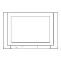
Identification and function of controls located on the front panel of the TV set.
Description of input and output connectors found on the side panel of the TV.
Defines the applicability of specifications and outlines testing methodologies.
Detailed technical parameters and features of the television set.
Steps for adjusting the picture focus using specific patterns and controls.
Procedures for optimizing color purity and screen convergence for accurate display.
Method for adjusting screen voltage for optimal picture display and clarity.
Process for setting white balance parameters for accurate color reproduction.
Steps for configuring deflection parameters to ensure proper picture geometry.
Fine-tuning of various horizontal and vertical deflection parameters for picture alignment.
Initial data settings for deflection adjustments based on specific TV models.
Default data settings managed by the EEPROM master for system operation.
Configuration options for various TV features, modes, and functionalities.
Settings for On-Screen Display menus and supported language options.
Conditions for operation stop and sound pre-scaler settings.
Specific adjustments for various option parameters for system customization.
Diagram and description of the special service remote control buttons and their usage.
Diagnostic steps for issues related to picture or sound output problems.
Diagnostic steps for issues where there is no raster or no sound output.
Further diagnostic steps for problems related to the absence of a raster scan.
Diagnostic flowcharts for cases with no picture and no sound output.
Visual layout of the main printed circuit board with component identification.
Visual layout of the side A/V input/output printed circuit board.
Diagram illustrating the interconnected functional blocks of the TV system.
Illustration showing the exploded view and assembly of TV components.
List of part numbers and descriptions for components in the exploded view.
Comprehensive list of all replaceable components including ICs, transistors, resistors, capacitors, and accessories.
Detailed circuit diagram of the CW62B chassis, showing component interconnections.
Reference number for the specific service sheet pertaining to the TV model.
| Display Technology | CRT |
|---|---|
| Aspect Ratio | 4:3 |
| Sound Output | Mono |
| Screen Size | 21 inches |
| Inputs | Composite |