- 9 -
LGE Internal Use Only
Copyright © LG Electronics. Inc. All right reserved.
Only for training and service purposes
- 24MT44A (HDMI)
4. Final Assembly Adjustment
4.1. White Balance Adjustment
4.1.1. Overview
▪ W/B adj. Objective & How-it-works
(1) Objective: To reduce each Panel's W/B deviation
(2) How-it-works : When R/G/B gain in the OSD is at 192, it
means the panel is at its Full Dynamic Range. In order to
prevent saturation of Full Dynamic range and data, one of
R/G/B is xed at 192, and the other two is lowered to nd
the desired value.
(3) Adjustment condition : normal temperature
1) Surrounding Temperature : 25 °C ± 5 °C
2) Warm-up time: About 5 Min
3) Surrounding Humidity : 20 % ~ 80 %
4) Before White balance adjustment, Keep power on
status, don’t power off
* Adj. condition and cautionary items
(1) Lighting condition in surrounding area surrounding lighting
should be lower 10 lux. Try to isolate adj. area into dark
surrounding.
(2) Probe location: Color Analyzer (CA-210) probe should
be within 10cm and perpendicular of the module surface
(80°~ 100°)
(3) Aging time
1) After Aging Start, Keep the Power ON status during
5 Minutes.
2) In case of LCD, Back-light on should be checked
using no signal or Full-white pattern.
4.1.2. Equipment
(1) Color Analyzer: CA-210 (NCG: CH 9 / WCG: CH12 / LED:
CH14)
(2) Adj. Computer (During auto adj., RS-232C protocol is
needed)
(3) Adjust Remocon
(4) Video Signal Generator MSPG-925F 720p/204-
Gray(Model: 217, Pattern: 49)
* Color Analyzer Matrix should be calibrated using CS-1000
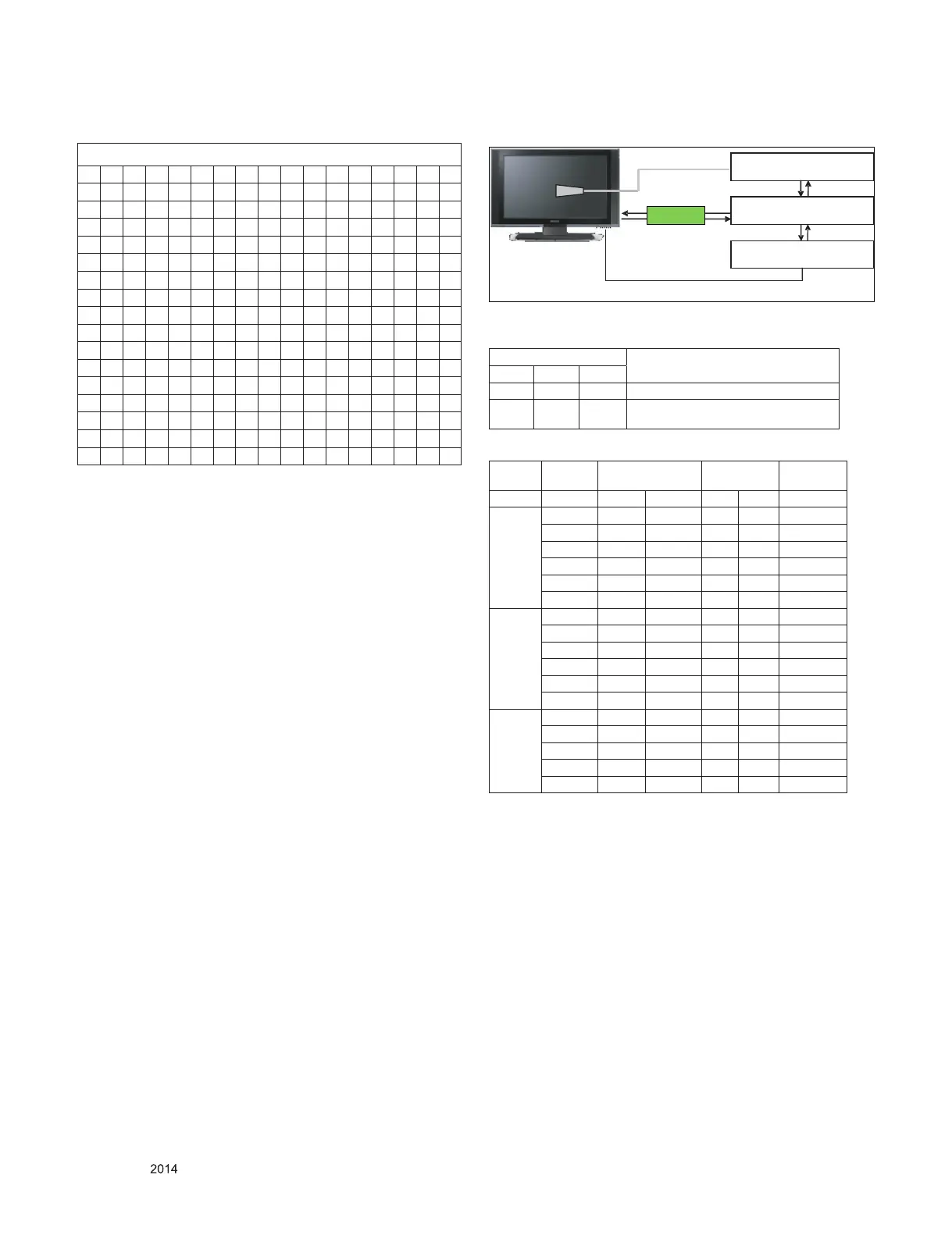
4.1.3. Equipment connection
4.1.4. Adjustment Command (Protocol)
(1) RS-232C Command used during auto-adj.
(2) Adjustment Map
RS-232C COMMAND
Explantion
CMD ID DATA
wb 00 00 Begin White Balance adjustment
wb 00 ff
End White Balance adjustment
(internal pattern disappears )
Adj. item
Command
(lower caseASCII)
Data Range
(Hex.)
Default
(Decimal)
CMD1 CMD2 MIN MAX
Cool
R Gain j g 00 C0
G Gain j h 00 C0
B Gain j i 00 C0
R Cut
G Cut
B Cut
Medium
R Gain j a 00 C0
G Gain j b 00 C0
B Gain j c 00 C0
R Cut
G Cut
B Cut
Warm
R Gain j d 00 C0
G Gain j e 00 C0
B Gain j f 00 C0
R Cut
G Cut
Co lo r Analyzer
Co m pu ter
Pattern Generator
RRGB Cable S-2 32C
RS-232C
RS-232C
Probe
Signal Source
* If TV internal pattern is used, not needed
DFT JIG
** HDMI : 256Bytes
0 1 2 3 4 5 6 7 8 9 A B C D E F
0 00 FF FF FF FF FF FF 00 1E 6D CA 59 01 01 01 01
10 01 17 01 03 80 34 1D 78 EA 53 4D A3 56 4F 9E 26
20 0F 47 4A 21 08 00 81 80 81 C0 71 40 B3 00 81 40
30 90 40 95 00 A9 C0 66 21 56 AA 51 00 1E 30 46 8F
40 33 00 09 25 21 00 00 1A 02 3A 80 18 71 38 2D 40
50 58 2C 45 00 09 25 21 00 00 1E 00 00 00 FD 00 38
60 3D 1E 45 0F 00 0A 20 20 20 20 20 20 00 00 00 FC
70 00 32 44 20 48 44 20 4C 47 20 54 56 0A 20 01 30
80 02 03 21 F1 4F 84 05 03 02 20 22 10 11 13 12 14
90 1F 07 16 01 26 11 07 50 09 7F 07 65 03 0C 00 10
A0 00 02 3A 80 18 71 38 2D 40 58 2C 45 00 09 25 21
B0 00 00 1A 01 1D 80 18 71 1C 16 20 58 2C 25 00 09
C0 25 21 00 00 9E 01 1D 00 72 51 D0 1E 20 6E 28 55
D0 00 09 25 21 00 00 1E 01 1D 80 D0 72 1C 16 20 10
E0 2C 25 80 09 25 21 00 00 9E 02 3A 80 D0 72 38 2D
F0 40 10 2C 45 20 09 25 21 00 00 1E 00 00 00 00 6F