24
Plasma Fall 2008 42PG20
X Board Removal (continued)
Lay the Plasma down carefully on a padded surface.
Make sure AC is removed and remove the Back Cover and the Stand.
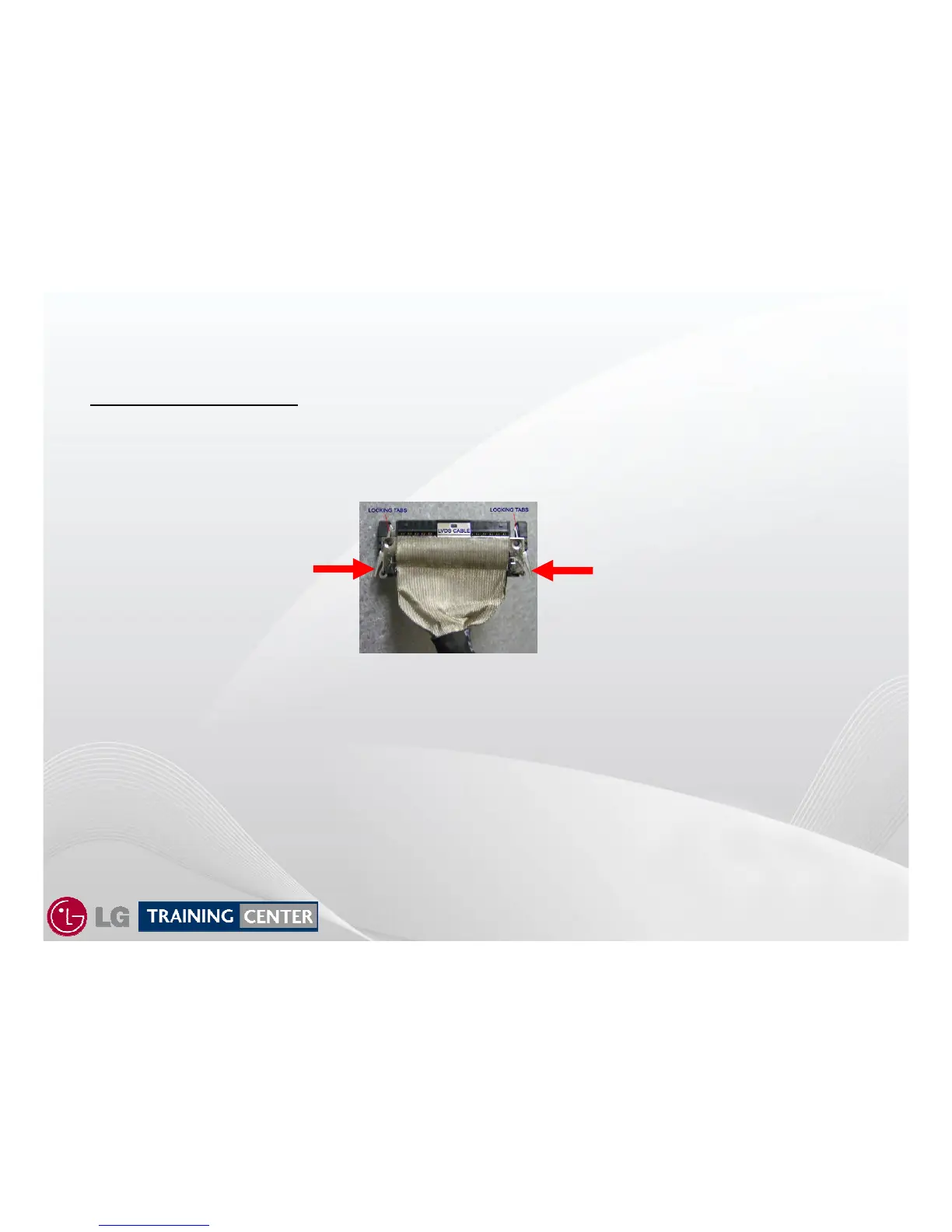
Carefully remove the LVDS Cable P121 from the Control Board by pressing the Locking Tabs together and
Pull the connector straight back to remove the cable see illustration below. (This prevents damage).
(A) Remove the Stand mounting support plastic piece.
(B) Remove the Stand Metal Support Bracket, unplug AC ground lug.
(C) Remove the 2 screws from the decorative black plastic piece around side input jacks (Marked B) and remove.
(D) Remove the 2 screws at the top of the Main Board Mounting Bracket and peel the tape from the bottom. Remove
connector P303 and JK501. Carefully reposition the Main Board and Mounting Bracket up and off to the right side.
(E) Remove the metal support Brackets marked “E”.
(F) Remove the 13 screws holding the Heat Sink and carefully lift it straight up and off (remember that the TCP IC’s are
located under the HEAT SINK ).
X-DRIVE PWBs REMOVAL:
Disconnect all TCP ribbon cables from the defective X-Drive PWB. Remove the 5 screws holding the PWB in place.
Remove the PWB. Reassemble in reverse order. Recheck Va/Vs/VScan/-VY/Z-Drive.
X Circuit Board Removal Continued
X Circuit Board Removal Continued
Press
Inward
Press
Inward
LVDS Cable Connector


 To Next Page