92
Plasma Fall 2008 42PG20
Control PWB Connector P160 to Y
Control PWB Connector P160 to Y
-
-
SUS P101 Voltages and Resistance
SUS P101 Voltages and Resistance
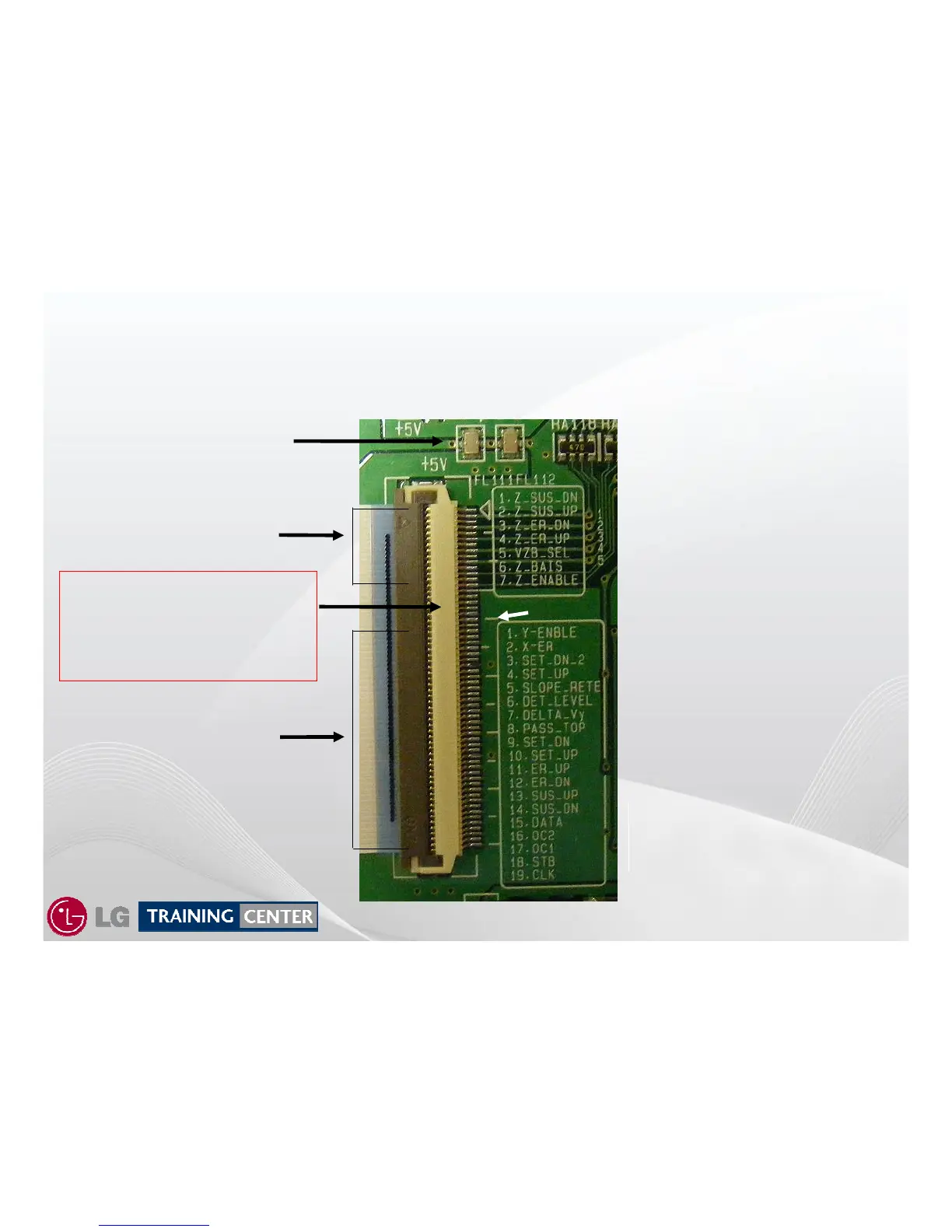
P160 These pins are very close together. When taking Voltage measurements use Caution.
In other words, there is a
ground between each pin
except the +5V area.
Actual Pin 1 (ground) 2 (Z-SUS-
DN) 3 (ground) 4 (Z-SUS-UP) 5
(ground), etc….
Remember, this connector has
many more pins than the labels
indicate.
This shows the Pin Labeling
that is shown on the silk
screening.
This connector is a little
confusing in its labeling.
It is actually a 60 pin connector.
This labeling refers to P160 pin
ID. This too has ground
between each pin. These are
responsible for Z Drive signals.
14 Pins related to Z-SUS
39 Pins related to Y-SUS
Pins 17, 18, 19, 20 and 21
Deliver +5V to the Control PWB
from the Y-SUS.
Easy to check using 20
th
hash
mark.
20
th
hash mark.
FL111 and FL112 5V Fuse


 To Next Page