Copyright © LG Electronics. Inc. All rights reserved.
Only for training and service purposes
2) Egde Direct LED models (applied only LGD Module) in LGEKR
(GUMI for Winter Season)
▪ Standard color coordinate and temperature using CA-
210(CH-14) – by aging time
5.2. Ship-out mode check (In-stop)
▪ After nal inspection, press In-Stop key of the Adj. R/C and
check that the unit goes to Stand-by mode
6. Audio
6.1. Audio input condition
1) Only DVI PC Input
6.2. Specication
7. GND and HI-POT Test
7.1. GND & HI-POT auto-check preparation
1) Check the POWER CABLE and SIGNAL CABE insertion
condition
7.2. GND & HI-POT auto-check
1) Pallet moves in the station. (POWER CORD / AV CORD is
tightly inserted)
2) Connect the AV JACK Tester.
3) Controller (GWS103-4) on.
4) GND Test (Auto)
- If Test is failed, Buzzer operates.
- If Test is passed, execute next process (Hi-pot test).
Remove A/V CORD from A/V JACK BOX)
5) HI-POT test (Auto)
- If Test is failed, Buzzer operates.
- If Test is passed, GOOD Lamp on and move to next
process automatically.
7.3. Checkpoint
1) Test voltage
- GND: 1.5KV/min at 100mA
- SIGNAL: 3KV/min at 100mA
2) TEST time: 1 second
3) TEST POINT
- GND Test = POWER CORD GND and SIGNAL CA-
BLE GND.
- Hi-pot Test = POWER CORD GND and LIVE & NEU-
TRAL.
4) LEAKAGE CURRENT: At 0.5mArms
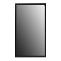
8. EYE Q Green Inspection
8.1 Method
1) Connect the Power and IR+Brightness Sensor cable to the
set.
2) Turn on the Signage SET.
3) Press “P-Only→ Exit → EYE” Button on the adjustment of
R/C.
4) Green Eye-Check Box on the screen after 3 seconds.
5) Cover the IR+Brightness Cable Assy with your hands, hold
it for 3 second
6) If normal operation is indicated the "OK " on the screen
7) If the "NG ", replace the IR+Brightness Cable Assy or Sen-
sor.
8) Please test again after changing the cable.
9) Please Press the In-Stop Button after completing the test.
[Note] Check the sensor data on the screen, make certain that
data is below 20. If data isn’t below 20 in 3 seconds, EYE
Q sensor would be bad. You should change EYE Q sen-
sor.
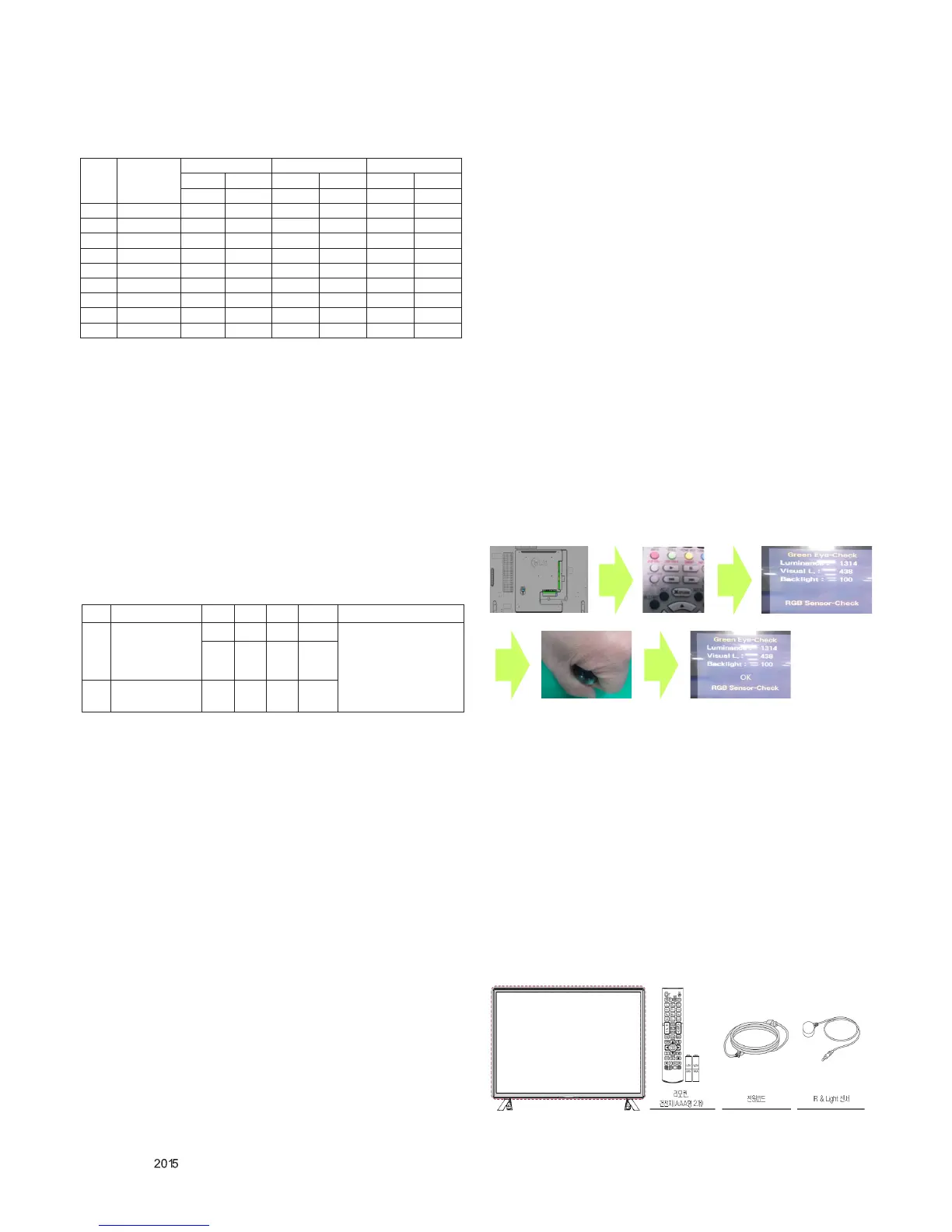
8.2 Pixel Sensor Inspection Manual
* Pixel Sensor Kit Parts
- SET / Power Cord / IR+Brightness Cable Assy / Remote
Control
No. Item Min Typ Max Unit Remark
1.
Audio practical
max Output, L/R
(Distortion=10%
max Output)
9.0 10.0 12.0 W
Measurement condition
EQ Off
AVL Off
Clear Voice Off
8.5 8.9 9.8 Vrms
2.
Speaker (8Ω
Impedance)
10.0 14.0 W
Net
Cast
3.0
Aging time
(Min)
Cool Medium Warm
X y x y x y
271 270 286 289 313 329
1 0-2 280 282 295 301 322 341
2 3-5 279 281 294 300 321 340
3 6-9 278 280 293 299 320 339
4 10-19 277 279 292 298 319 338
5 20-35 276 277 291 296 318 336
6 36-49 274 275 289 294 316 334
7 50-79 273 273 288 292 315 332
8 80-119 272 271 287 290 314 320
9 Over 120 271 270 286 289 313 329

 Loading...