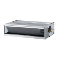
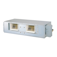
This document is an installation manual for an LG Ceiling Concealed Duct Air Conditioner, model number MFL67939906. It provides comprehensive instructions for installation, operation, and maintenance, emphasizing safety precautions and energy-saving tips.
Function Description
The LG Ceiling Concealed Duct Air Conditioner is designed to provide cooling and dehumidifying functions for indoor spaces. It is a duct-type air conditioner, meaning it is installed above the ceiling and distributes conditioned air through ducts. The unit is controlled via a wired remote controller, which allows for various settings and operational modes. The system supports both single-unit and multi-unit (group) control configurations.
Important Technical Specifications
The manual provides detailed dimensions and hanging bolt locations for different capacities of the indoor unit, ranging from 5/7 kW to 13.4/15.8 kW. Key dimensions (A, B, C, D, E, F, G, H, I, J) are specified in millimeters, with examples like 933.4 mm for length (A) and 619.2 mm for width (C) for smaller units, and 1283.4 mm for length (A) for larger units.
Wiring Connection:
- Normal Cross-Sectional Area for Power Wiring:
- 5/7/10 kW: 2.5 mm²
- 13.4/15.8 kW: 6.0 mm²
- Normal Cross-Sectional Area for Connecting Wiring (Indoor/Outdoor Unit): 0.75 mm²
- Extension Cable for Remote Controller: 2547 1007 22# 2 core 3 shield, 5 m or above. The maximum cable length for the wired remote controller is 50 m.
Drain Piping:
- Outside Diameter of Drain Connection: 32 mm
- Piping Material: Polyvinyl chloride pipe VP-25 and pipe fittings.
- Drain Slope: Downward inclination of 1/50 to 1/100.
- Heat Insulation Material for Drain Piping: Polyethylene foam with a thickness of more than 8 mm.
Refrigerant Piping Heat Insulation:
- Material: Heat insulation material with excellent heat-resistance (over 120 °C).
- Minimum Thickness for Connecting Pipe Insulation: 5 mm.
- Additional Insulation for High Humidity: Adiabatic glass wool with a thickness of 10 to 20 mm for units in ceiling atmospheres with dew point temperatures above 23 °C.
Static Pressure Settings (mmAq/Pa):
The manual includes detailed tables for External Static Pressure (E.S.P.) settings for various models (ABNQ18GM1A2, ABNQ24GM1A2, ABNQ36GM2A2, ABNQ48GM3A2, ABNQ54GM3A2) across different CMM (Cubic Meters per Minute) and fan speed levels (HIGH, MID, LOW). These settings are crucial for optimizing airflow and ensuring proper operation based on ductwork resistance. For example, for ABNQ18GM1A2 at HIGH fan speed and 16.5 CMM, the E.S.P. values range from 85 mmAq (32:01 setting) to 133 mmAq (32:11 setting). Factory set E.S.P. values are also provided, such as 8(78) mmAq for ABNQ18GM1A2 and ABNQ24GM1A2, and 10(98) mmAq for ABNQ36GM2A2. Maximum E.S.P. values are listed for each model, e.g., 106 for ABNQ18GM1A2 and 115 for ABNQ24GM1A2.
Usage Features
Remote Controller:
The wired remote controller is the primary interface for operating the air conditioner. It allows users to:
- Adjust temperature (up/down buttons).
- Select fan speed (FAN SPEED button).
- Enter and exit operational modes (OPER MODE button).
- Access installer settings for advanced configurations.
Installer Settings (Optional Operation):
The manual details several installer settings accessible via the remote controller, typically by pressing the △ and OPER MODE buttons simultaneously for more than 3 seconds:
- Test Run Mode (Code 01): Initiates a cooling, strong wind, and compressor-on operation for approximately 18 minutes to confirm installation.
- Setting Address of Central Control (Code 02): Configures the network address (group number and indoor unit number) for central control systems.
- Thermistor Setting (Code 04): Selects the temperature sensor location (remote controller, indoor unit, or 2TH) for room temperature judgment.
- Remote Controller Master/Slave Setup (Code 07): Designates a remote controller as master or slave in group control or 2-remote controller setups. The master unit operates based on its settings, while slave units follow.
- Celsius / Fahrenheit Switching (Code 12): Toggles the temperature display between Celsius and Fahrenheit (optimized for U.S.A.). In Fahrenheit mode, temperature adjustments occur in 2-degree increments.
- E.S.P. Setting (Code 03): Adjusts the External Static Pressure for each fan speed level (Lo, Med, Hi) to match the ductwork resistance, with values ranging from 0 to 255. This is a critical setting that must be performed by a certified technician.
- Static Pressure Step Setting (Code 32): Divides the product's static pressure into 11 steps for fine-tuning, applicable only to duct-type units.
DIP Switch Settings:
The indoor PCB features DIP switches for specific configurations:
- SW3 (Group Control): Sets the unit as Master (OFF) or Slave (ON) for group control. Default is OFF (Master).
- SW4 (Dry Contact Mode): Selects between Wired/Wireless remote controller mode (OFF) or Manual/Auto operation mode (ON) for dry contact functionality. Default is OFF.
- SW5 (Installation): Enables (OFF) or disables (ON) continuous fan operation removal. Default is OFF (Working).
Energy Saving Tips:
The manual provides tips to minimize power consumption:
- Avoid excessive cooling.
- Block sunlight with blinds or curtains.
- Keep doors and windows closed tightly.
- Adjust airflow direction for better circulation.
- Speed up the fan for quick cooling/warming.
- Ventilate regularly.
- Clean the air filter every 2 weeks.
Maintenance Features
Installation Inspection:
- Inspection Hole: A 600 x 600 mm inspection hole is required in the ceiling for maintenance and filter cleaning.
- Gas Leakage Inspection: Always inspect for gas leakage after installation and repair.
Drainage Maintenance:
- Drain Test: After installation, water should be fed into the flexible drain hose to check for leakage before connecting it to the main drain pipe.
- Air Filter Cleaning: The air filter should be removed and cleaned regularly (every 2 weeks) to prevent blockages and maintain cooling/dehumidifying efficiency.
General Maintenance:
- Cleaning: Use a soft cloth for cleaning; avoid wax, thinner, or strong detergents to prevent damage to the unit's appearance.
- Professional Service: For any product malfunction, property damage, personal injury, or death, contact a qualified service technician. Do not disassemble or repair the product randomly. If the product is submerged in water, contact the service center.
- Power Cord: Replace damaged power cords with special wiring or assemblies available from the manufacturer or service agent.
The manual strongly emphasizes that installation and repairs must be performed by qualified personnel in accordance with national wiring standards and local building codes to ensure safety and proper operation. Failure to follow instructions can lead to equipment malfunction, property damage, personal injury, or death.