8 Auxiliary Heat Control
Assembly Diagram
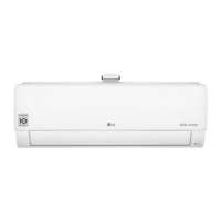
Lock nut
Conduit
mounting
plate
Conduit
Knockout for
horizontal-left
Knockout for upflow
Step 7. Remove knockout and connect conduit.
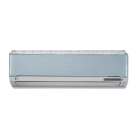
Step 5. Install heater. The bracket should be inserted in
the provided slot.
Step 6. Attach the heater to panel using the existing holes
and screws.
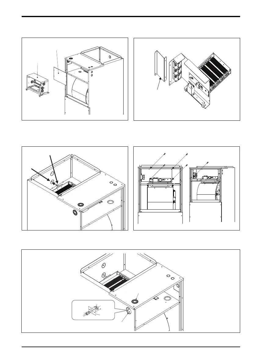
Control Box
Heater Panel
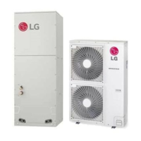
Step 3. Pull out control box. Remove heater panel.
Step 4. Remove the additional mounting bracket (shown
in the figure) while installing 5 kW and 10 kW
heater with NJ chassis.