Assembly Diagram
Installation Manual 9
ENGLISH
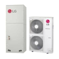
Step 9. Insert control box. Connect the three thermistors(CN_Pipe out, CN_Pipe in and CN_Room, CN_Out) , CN_EEV
and CN_Motor1 connector, Heater connector in control box. Waste the harness and replace new one. (CN_Motor)
The new harness is provided with the Electric Heater accessories. (It may vary depending on the model)
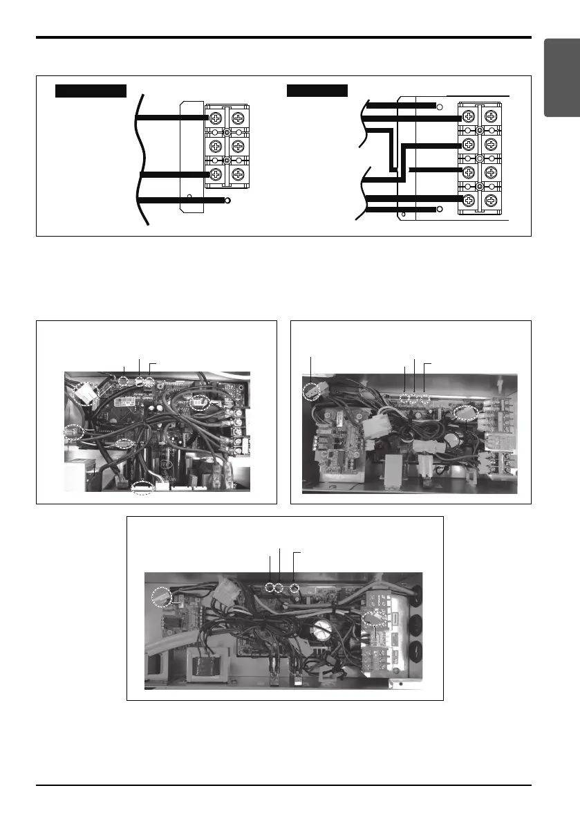
L1
L2
EARTH
POWER INPUT
1 Ø 208/230 V 60 Hz
POWER INPUT 1
1 Ø 208/230 V 60 Hz
POWER INPUT 2
1 Ø 208/230 V 60 Hz
3, 5, 8, 10 kW Heater
15, 20 kW Heater
L1
L2
L3
L4
EARTH
EARTH
Step 8. Connect power cable to terminal block.
Connect earth cable to heater panel.
CN_Pipe out (Red)
CN_Pipe in (White)
(Multi V)
CN_EEV (White)
CN_Motor1 (White)
CN_EEV (White)
CN_Motor1 (White)
CN_Room (Y
ellow)
Terminal BlockTerminal Block
CN OutCN Out
CN_Motor1 (white)
CN_Motor1 (white)
Heater connectorHeater connector
Heater connector
(Single & Multi)NJ
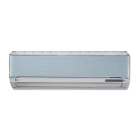
CN_EEV (White)
CN_Motor1 (White)
CN_Pipe out (Red)
CN_Pipe in (White)
CN_Room (Yellow)
Terminal Block
CN Out
CN_Motor1 (white)
CN_Motor1 (white)CN_Motor1 (white)
Heater connector
Heater connector
Heater connector
(Single & Multi)NK
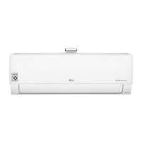
CN_EEV (White)
CN_Motor1 (White)
Terminal Block
CN Out
CN_Pipe out (Red)
CN_Pipe in (White)
CN_Room (Yellow)
CN_Motor1 (white)CN_Motor1 (white)
CN_Motor1 (white)
Heater connector
Heater connectorHeater connector