GUIDELINES | 197
Application Guidelines
Due to our policy of continuous product innovation, some specications may change without notication.
© LG Electronics U.S.A., Inc., Englewood Cliffs, NJ. All rights reserved. “LG” is a registered trademark of LG Corp.
General Drain Piping Information
All ducted indoor units generate water during cooling operation,
therefore, how to properly handle this condensation must be consid-
ered. Depending on the location of the indoor unit, condensation can
be drained directly to the outside of the building, or a common indoor
unit drainage piping system can be installed.
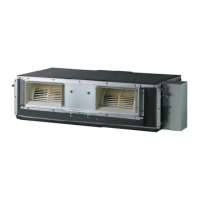
Ducted Unit Drain Information
High Static and Low Static Ducted indoor units include factory-in-
stalled drain pumps. When the bottom surface of the indoor unit is at
an elevation below the receiving building drain line connection, install
an inverted trap at the top of the condensate pump discharge riser
before connection to the building drain pipe.
When the receiving drain line is mounted horizontal, connect the
inverted trap to the top half of the pipe. The connection point of the
inverted trap to the building drain pipe must always be to the top half
of the pipe and must never be over 45° either side of the upper most
point of the horizontal building drain line.
If connecting to a vertical drain line or plumbing system vent line,
connect the IDU condensate pump discharge line using a Y-45 tting
with the double end of the Y-45 tting facing up. When connecting to
a vertical drain line include an inverted trap at the top of the IDU con-
densate pump discharge riser before connection to the Y-45 tting.
Vertical / Horizontal Air Handler Unit Drain Information
Vertical / Horizontal Air Handler units have a gravity drain.
• Avoid blocking lter access panel when connecting the condensate
drain lines.
• An additional external condensate line must run from the unit into
the pan.
• The entire condensate line must be drained from the external
condensate pan.
• Point the drain hose downward for easy drain ow.
• Do not use pipe joint connection or PVC/CPVC for the unit drain
line connection. Use Teon
®
tape.
Indoor Unit Drain Type
Drain Pipe Dia.
(ID, in.)
BH, B8, M2, M3 Frame
High Static Ducted
27-1/2 in. Lift
Drain Pump,
Factory Installed
Ø1
L1, L2, L3 Frame
Low Static Ducted
NJ, NK Frame Vertical / Horizontal
Air Handler Unit
Gravity Ø1
Table 155: Indoor Unit Drainage Specications.
1/50~1/100
slope
Hanger distance
3.3~4.9 feet
Hanger Bracket
Flexible drain hose
Insulation
Metal
clamp
Max.
11-13/16 inches
PVC Piping
PVC Elbow
Drain pump
Figure 69: High Static and Low Static Ducted Indoor Unit Drain Pump to
Drain Piping System.
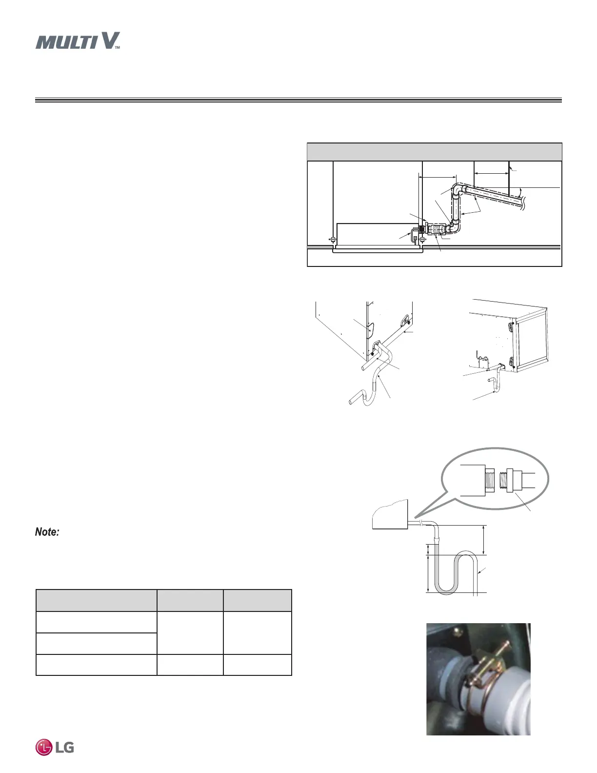
Clamp the Flexible Drain Hose Connection
Flexible Drain Hose
Ducted indoor units and vertical / horizontal air handler units include a factory-provided flexible drain
hose (with one or two clamps) to connect the indoor unit to the drain piping / drain piping system.
Figure 70: Vertical / Horizontal Air Handler Unit Drain Piping System.
APPLICATION GUIDELINES
General Drain Piping Information
A eld-supplied external condensate pan must be installed underneath
the entire vertical / horizontal air handler unit. If not, damage may result
due to condensate overow.
D
r
a
i
n
f
o
r
U
p
f
l
o
w
I
n
s
t
a
l
l
a
t
i
o
n
s
H
o
r
i
z
o
n
t
a
l
-
L
e
f
t
D
r
a
i
n
A
c
c
e
s
s
H
o
l
e
A
i
r
F
i
l
t
e
r
C
o
v
e
r
M
a
i
n
d
r
a
i
n
a
l
o
n
g
w
i
t
h
s
u
i
t
a
b
l
e
t
r
a
p
.
(
A
f
i
e
l
d
-
s
u
p
p
l
i
e
d
t
r
a
p
w
i
t
h
s
u
f
f
i
c
i
e
n
t
d
e
p
t
h
c
a
n
b
e
u
s
e
d
.
S
t
a
n
d
a
r
d
-
s
i
z
e
d
t
r
a
p
s
a
r
e
n
o
t
s
u
f
f
i
c
i
e
n
t
.
R
e
f
e
r
t
o
t
h
e
U
-
T
r
a
p
S
p
e
c
i
f
i
c
a
t
i
o
n
s
f
i
g
u
r
e
f
o
r
t
h
e
r
e
c
o
m
m
e
n
d
e
d
c
o
n
d
e
n
s
a
t
e
t
r
a
p
.
)
S
u
p
p
l
e
m
e
n
t
a
r
y
d
r
a
i
n
w
i
t
h
p
r
o
p
e
r
t
r
a
p
.
(
F
i
e
l
d
-
s
u
p
p
l
i
e
d
k
i
t
c
a
n
b
e
u
s
e
d
.
)
D
r
a
i
n
f
o
r
H
o
r
i
z
o
n
t
a
l
-
L
e
f
t
I
n
s
t
a
l
l
a
t
i
o
n
s
Figure 71: Vertical / Horizontal Air Handler Unit U-Trap Specications.
U-Trap
B
C
A ≥
2-9/16 inch
B ≥ 2C
C ≥ 2 x SP
SP = External Pressure
(in. WG)
Ex) External Pressure
= 0.4 in. WG
A ≥ 2-9/16 inches
B ≥ 1-7/12 inches
C ≥ 13/16 inches
A
Applied U-Trap Dimensions
• Install the U-Trap to prevent leaks
caused by blocking the intake air filter.
3/4 inch
connector
Figure 72: Flexible Drain Hose Connection.
 Loading...