Do you have a question about the LG AUUH1008C and is the answer not in the manual?
Explains the nomenclature for LG indoor unit models.
Explains the nomenclature for LG outdoor unit models.
Safety guidelines for installing the air conditioner unit.
Explains the meaning of warning and caution symbols used in the manual.
Lists and categorizes indoor unit models by type and capacity.
Lists and categorizes outdoor unit models by type and capacity.
Lists models for branch kits and their specifications.
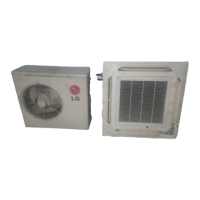
Shows the external appearance of various indoor unit types.
Shows the external appearance of various outdoor unit models.
Provides detailed dimensions for indoor cassette units (TE, TF, TD).
Detailed specifications for ceiling cassette 4-way indoor units.
Shows possible combinations of indoor and outdoor units for MPS Variable systems.
Instructions for installing cassette type indoor units.
Lists standard accessories included with the unit.
Lists optional accessories available for the unit.
Steps for preparing refrigerant pipes before connecting to the indoor unit.
Instructions for preparing the remote controller for installation.
Guidance on selecting the optimal location for the AUUH728C outdoor unit.
Required space specifications for individual installation of AUUH728C.
Specifies clearances for inlet air when unit is surrounded by walls or has obstructions.
Specifies clearance requirements when there is an obstruction above the unit.
Required space specifications for individual installation of AUUH1008C.
Specifies clearance requirements when there is an obstruction above the unit.
Safety precautions and guidelines for safely carrying the product.
Method for calculating and performing additional refrigerant charging for AUUH488C.
Method for calculating and performing additional refrigerant charging for AUUH728C/AUUH1008C.
Describes types of branch pipes based on indoor capacity and installation.
Lists accessories required for branch kit installation.
Specifications for branch pipe connection parts (gas and liquid).
Instructions for setting the JIG_SW for auto addressing.
Instructions for setting ZONE SW1 based on indoor unit configuration.
Step-by-step procedure for performing auto addressing.
Important precautions to take before and during test running the unit.
List of items to check after completing the installation.
Details the functions of the main unit control system.
Explains how the unit operates in cooling mode based on temperature.
Explains the soft dry operation mode and its conditions.
Details fuzzy logic operation for cooling mode.
Details the jet cool mode for rapid cooling operation.
Describes the auto restart function after power failure.
Explains the sleep timer function for adjusting operation time.
How to operate the unit manually when the remote is lost.
Explains buzzer sounds for key inputs and appliance status.
Details the functions of various buttons on the convertible remote controller.
Details the jet cool mode for rapid cooling operation.
Describes the chaos swing mode for automatic louver movement.
Explains the operation display and buttons on the CST type remote controller.
Explains the operation display and buttons on the duct type remote controller.
Explains the two thermistor system for temperature control.
How to adjust air volume based on ceiling height for cassette units.
ESP settings for duct units without a zone system.
ESP settings for duct units with a zone system.
Lists key features and capabilities of the simple central control system.
Explains the parts and functions of the simple central control unit.
Procedure for setting indoor unit addresses using a wired remote.
Procedure for setting indoor unit addresses using a wireless remote.
Procedure for monitoring the set addresses of indoor units.
Ability to monitor and control individual or groups of AC units.
Features for managing groups of air conditioners.
The system's self-diagnosis capabilities for error detection.
User-friendly interface for easy operation and schedule setting.
Functionality for setting automatic operation schedules for energy saving.
Built-in battery for stable operation during temporary power failures.
General monitoring and control functions of the central system.
Manages AC units via grouping and installation position setup.
Enables setting weekly schedules for all, group, or individual AC operations.
Electrical schematic for cassette type indoor unit control devices.
Electrical schematic for duct type indoor unit control devices.
Electrical schematic for convertible type indoor unit control devices.
Component layout schematic for outdoor units.
Wiring diagram for cassette type indoor units.
Wiring diagrams for duct type indoor units (BH, BG, BR chassis).
Wiring diagrams for convertible type indoor units (VE, VB chassis).
Wiring diagram for AUUH488C outdoor unit.
Wiring diagram for AUUH728C outdoor unit.
Wiring diagram for AUUH1008C outdoor unit.
Component layout diagram for Cassette Type TE/TF/TD chassis.
Component layout diagram for Duct Type BH/BG chassis.
Component layout diagram for Convertible Type VB chassis.
Component layout for the AC part of VE chassis.
Component layout for the DC part of VE chassis.
Component layout diagram for the outdoor unit's component side.
Piping diagram for AUUH488C with Synchro Duo configuration.
Piping diagram for AUUH488C with Synchro Trio configuration.
Piping diagram for AUUH488C with Synchro Quartet configuration.
Piping diagram for AUUH728C with Synchro Duo configuration.
Piping diagram for AUUH728C with Synchro Trio configuration.
Piping diagram for AUUH728C with Synchro Quartet configuration.
Piping diagram for AUUH1008C with Synchro Duo configuration.
Piping diagram for AUUH1008C with Synchro Trio configuration.
Piping diagram for AUUH1008C with Synchro Quartet configuration.
Analyzes temperature and current differences to diagnose cycle issues.
Checks temperature and pressure to troubleshoot refrigeration cycle problems.
Troubleshooting steps when the product does not operate.
Troubleshooting steps when the remote controller is not working.
List of error codes and descriptions for indoor unit malfunctions.
List of error codes and descriptions for outdoor unit malfunctions.
Steps to troubleshoot issues with the indoor air sensor.
Steps to troubleshoot issues with indoor pipe sensors.
Troubleshooting steps for communication issues with wired remote control.
Troubleshooting steps for drain pump and float switch issues.
Steps to troubleshoot communication issues between indoor and outdoor units.
Troubleshooting steps for DC Peak (IPM Fault) issues.
Troubleshooting steps for Max. C/T errors.
Troubleshooting steps for C/T internal circuit errors.
Troubleshooting steps for Press S/W Open errors.
Troubleshooting steps for abnormal input voltage errors.
Troubleshooting steps for DC compressor position errors.
Troubleshooting steps for PSC Fault errors.
Troubleshooting steps for high D-pipe temperature in inverter mode.
Troubleshooting steps for high D-pipe temperature in constant mode.
Troubleshooting steps for various sensor errors (D-pipe, Air, Condenser, Suction, Heat sink).
Troubleshooting steps for capacity error issues.
Troubleshooting steps for EEPROM check sum errors.
Troubleshooting steps for phase error issues.
Troubleshooting steps for high condenser pipe sensor temperature.
Troubleshooting steps for high heat sink sensor temperature.
Details the works and shaft/service port positions for the liquid side 3-way valve.
Details the works and shaft/service port positions for the gas side 3-way valve.
Functionality for automatic louver swing up and down.
Operation mode that automatically sets indoor fan speed to low for dry operation.
How the unit operates in cooling mode based on intake air temperature.
Operation mode that automatically sets indoor fan speed to low for dry operation.
How the unit operates in cooling mode based on intake air temperature.
Operation mode that automatically sets indoor fan speed to low for dry operation.
How the unit operates in cooling mode based on intake air temperature.
Describes normal operation modes for compressor, fan, EEV, and 4-way valve.
Explains step control for compressor operation based on temperature differences.
Diagram showing cooling operation steps based on indoor/outdoor temperatures.
Diagram showing heating operation steps based on indoor/outdoor temperatures.
Explains the logic for Electronic Expansion Valve (EEV) control.
Describes the two-step fan control (Stop/Operation).
Explains phase control for fan speed based on outdoor temperature.
Conditions required for initiating the defrost process.
Specifies the duration of defrost process starting and stopping.
Details the sequence of operations during the defrost process.
Logic for equalizing oil levels between compressors.
Function to prevent compressor damage based on discharge pipe temperature.
Specific temperature thresholds and actions for discharge temperature control.
How outdoor pipe temperature affects compressor operation and error codes.
Function to detect and prevent abnormal operations due to sensor issues.
System behavior related to high/low pressure switch signals.
Exploded view of TE chassis ceiling cassette indoor units.
Exploded view of TF chassis indoor units.
Exploded view of TD chassis indoor units.
Exploded view of convertible VB chassis indoor units.
Exploded view of BH/BG chassis duct indoor units.
Exploded view of BR chassis duct indoor units.
Exploded view of convertible VE chassis indoor units.
Replacement parts list for the PT-HEC1 indoor unit.
Replacement parts list for the PT-HFC indoor unit.
Replacement parts list for the PT-HDC1 indoor unit.
| Brand | LG |
|---|---|
| Model | AUUH1008C |
| Category | Air Conditioner |
| Language | English |