3. TECHNICAL BRIEF
- 14 -
(1) Receiver Part
The Aero I transceiver uses a low-IF receiver architecture which allows for the onchip integration of
the channel selection filters, eliminating the external RF imagereject filters and the IF SAW filter
required in conventional super-heterodynearchitectures.
A. RF front end
RF front end consists of Front End Module(FL500) and Quad bandLNAsintegrated in transceiver
(U500).
The Received RF signals(GSM 925MHz ~ 960MHz, DCS 1805MHz ~ 1880MHzPCS 1930MHz ~
1990MHz) are fed into the antenna or Mobile switch. The Front End Module(FL500) is used to
control the Rx and Tx paths. And, the inputsignals VC1, VC2, VC3 of a FL501 are directly con-
nected to basebandcontroller to switch either Tx or Rx path on.
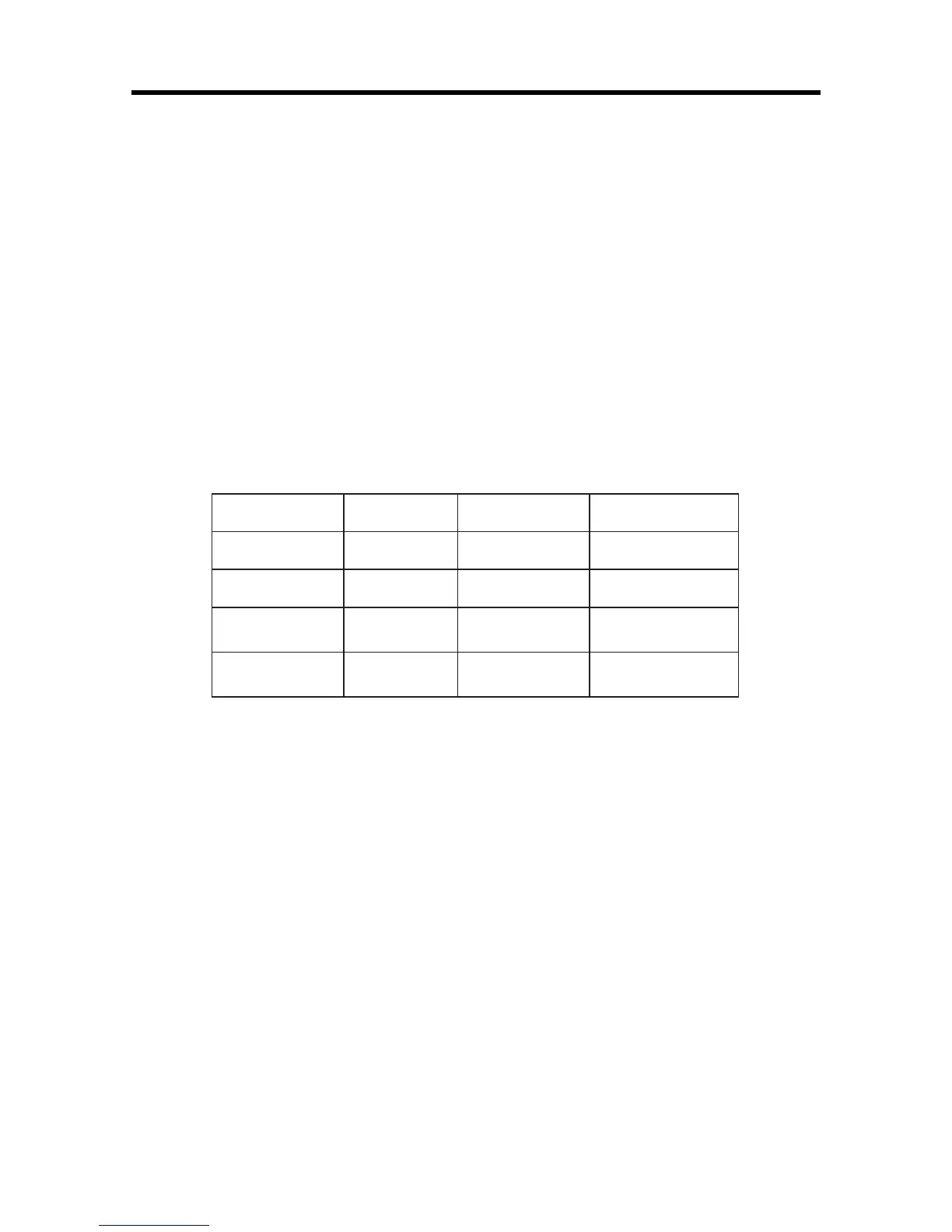
The logic and current is given below Table 3-1.
Three differential-input LNAsare integrated in SI4205. The GSM input supports the GSM850
(869-849 MHz) or E-GSM 900 (925-960MHz) bands. The DCS input supports theDCS 1800
(1805-1880 MHz) band. The PCS input supports the PCS 1900 (1930-1990MHz) band.
The LNA inputs are matched to the 150Ωbalanced output SAW filters through externalLC match-
ing networks. The LNA gain is controlled with the LNAG[1:0] and LNAC[1:0]bits in register 05h
(Figure 3-2).
 Loading...