3. TECHNICAL BRIEF
- 26 -
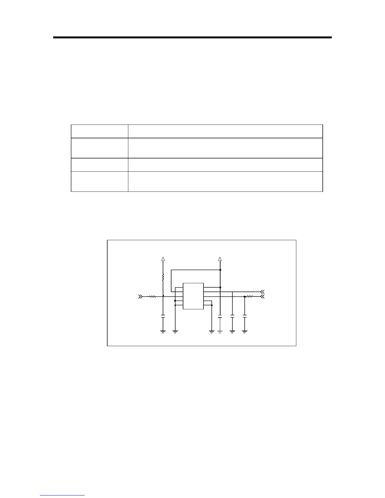
D. SIM interface
The AD6527 provides SIM Interface Module. The AD6527 checks status periodically
duringestablished call mode whether SIM card is inserted or not, but it doesn't check during
deepSleep mode. In order to communicate with SIM card, 3 signals SIM_DATA,
SIM_CLK,SIM_RST(GPIO_23)
are required. The descriptions about the signals are given by bellow Table 3-6 in detail.
Signals Description
LCD_DATA
LCD_CLK
SIM_RST
(GPIO_23)
This pin receives and sends data to SIM card.
This model can support only 3.0 volt interface SIM card.
Clock 3.25MHz frequency.
Reset SIM block
Table 3-6 SIM CONTRON SIGNALS DISCRIPTION
Figure 3-9 SIM Interface of AD6527
1
2
3
7
8
4
5
6
10
9
SIM_DATA
2V85_VSIM
OND1
R336
20K
R337
R338
J300
VPP
IO
OND5
OND4
VCC
RST
CLK
OND2
OND3
2V85_VSIM
SIM_RST
SIM_CLK
C315C314
NA
0
0
NA220n
1000p
C316 C317
E. Key interface
Include 5 column, 5 row and additional GPIO 35 for KEY_ROW5. The AD6527 detects
whetherkey is pressed or not by using interrupt method.
F. AD6537B Interrupt
AD6537B provides an active-high interrupt output signal. Interrupt signals are generated
bytheAuxiliary ADC, audio, and charger modules.

 Loading...