Do you have a question about the LG CJ65 and is the answer not in the manual?
Guidelines for safe handling, transport, storage, and repair of the pick-up module.
Procedures to prevent damage from electrostatic discharge to sensitive components.
Instructions and descriptions for accessing and using hidden key modes for diagnostics.
Steps for accessing and modifying EEPROM settings for service purposes.
Procedure for downloading and updating the device firmware via USB.
Step-by-step guide for updating device firmware wirelessly using a Bluetooth app.
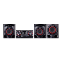
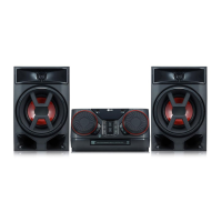
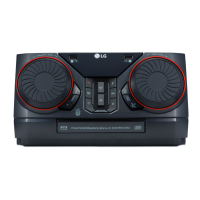
Technical specifications for the LG Mini Hi-Fi System, including power, inputs, and dimensions.
Visual diagrams showing the breakdown of the main chassis and cabinet components.
Details and diagrams of the packing materials and accessories included with the product.
Information related to the front speaker unit and its components.
Step-by-step instructions for disassembling the unit's main chassis parts.
Troubleshooting guide for common "no power" issues, including component checks.
Comprehensive troubleshooting flowcharts for various electrical faults and symptoms.
Visual examples of oscilloscope waveforms for key signal points during troubleshooting.
Diagram illustrating the electrical connections and wiring paths within the system.
High-level block diagrams showing the functional units and their interconnections.
Table detailing expected voltage levels for ICs, connectors, and capacitors.
Diagrams showing the layout of components on the SMPS, Main, Front, and MIC PCBs.
| Type | Home audio mini system |
|---|---|
| Cassette deck | No |
| Product color | Black, Red |
| Disc loading type | Front |
| Optical disc player | Yes |
| Number of optical discs | 1 discs |
| Coloration | Monochromatic |
| RMS rated power | - W |
| Number of speakers | - |
| Peak Music Power Output (PMPO) | 900 W |
| Equalizer bands quantity | 7 |
| Power source | AC |
| Power consumption (standby) | 0.5 W |
| Power consumption (typical) | 115 W |
| Supported radio bands | FM |
| Preset stations quantity | 50 |
| USB 2.0 ports quantity | 2 |
| Playback modes | Repeat |
| Disc types supported | CD-R, CD-RW |
| Playback disc formats | CD audio |
| Audio formats supported | MP3, WMA |
| Rear speaker depth | 230 mm |
|---|---|
| Rear speaker height | 363 mm |
| Main unit dimensions (WxDxH) | 350 x 251 x 163 mm |