Do you have a question about the LG CM7420 and is the answer not in the manual?
Precautions for handling the pick-up unit and general servicing.
Precautions for handling electrostatic sensitive devices (ESD).
Special modes accessible via hidden key combinations.
Procedures for accessing and managing EEPROM data.
Instructions for downloading firmware or software updates.
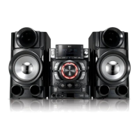
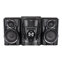
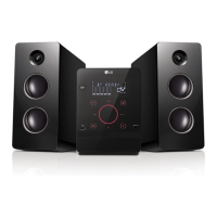
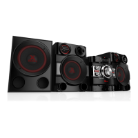
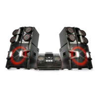
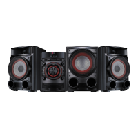
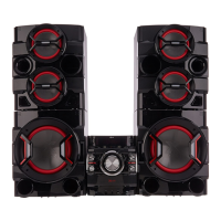
Technical specifications of the Mini Hi-Fi System.
Visual diagrams showing the assembly of the unit's components.
Troubleshooting guide for common sound issues.
Specific repair procedures for common faults.
Systematic troubleshooting steps for electrical problems.
Reference waveforms for diagnosing servo and motor issues.
Diagram illustrating the electrical connections between components.
Block diagram of the main system architecture.
Block diagram of the Switched-Mode Power Supply.
Detailed schematic of the power supply unit's circuit.
Circuit diagram for the main microcontroller unit.
Circuit diagram for PWM and filter sections.
Circuit diagram for the IR amplifier.
Circuit diagram for DSP, USB, and iPod functions.
Circuit diagram for RF and servo systems.
Circuit diagram for the Analog-to-Digital Converter.
Circuit diagram for the Beat Box feature.
Circuit diagram for the Vacuum Fluorescent Display.
Circuit diagram for volume control and LEDs.
Circuit diagram for microphone and portable inputs.
Table of voltage values for key ICs.
Top view layout of the SMPS printed circuit board.
Top view layout of the main printed circuit board.
Top view layout of the VFD printed circuit board.
Top view layout of MIC/Portable PCB.
Top view layout of the volume control PCB.
| Karaoke | No |
|---|---|
| Bass reflex | - |
| Speaker type | 4-way |
| Subwoofer type | Passive subwoofer |
| RMS rated power | 650 W |
| Number of speakers | 2 |
| Subwoofer included | Yes |
| Peak Music Power Output (PMPO) | 7200 W |
| Type | Home audio mini system |
| Product color | Black |
| Playback disc formats | CD audio |
| Audio formats supported | MP3 |
| Apple docking compatibility | Not supported |
| Power source | AC |