28 29
Caution
Trouble Symptom
Measurement Condition
1
2
1
2
1. Power Connection
2. Status Mode Of The Connection
When measuring power, be sure to wear insulated gloves to avoid an electric shock.
With Dryer Power On; Connector linked to Controller.
High
Mid High
Medium
High
Mid High
Medium
Tab Relay 1
Tab Relay 1 Burner Remark
Tab Relay 2
Heater 1 Heater 2
Remark
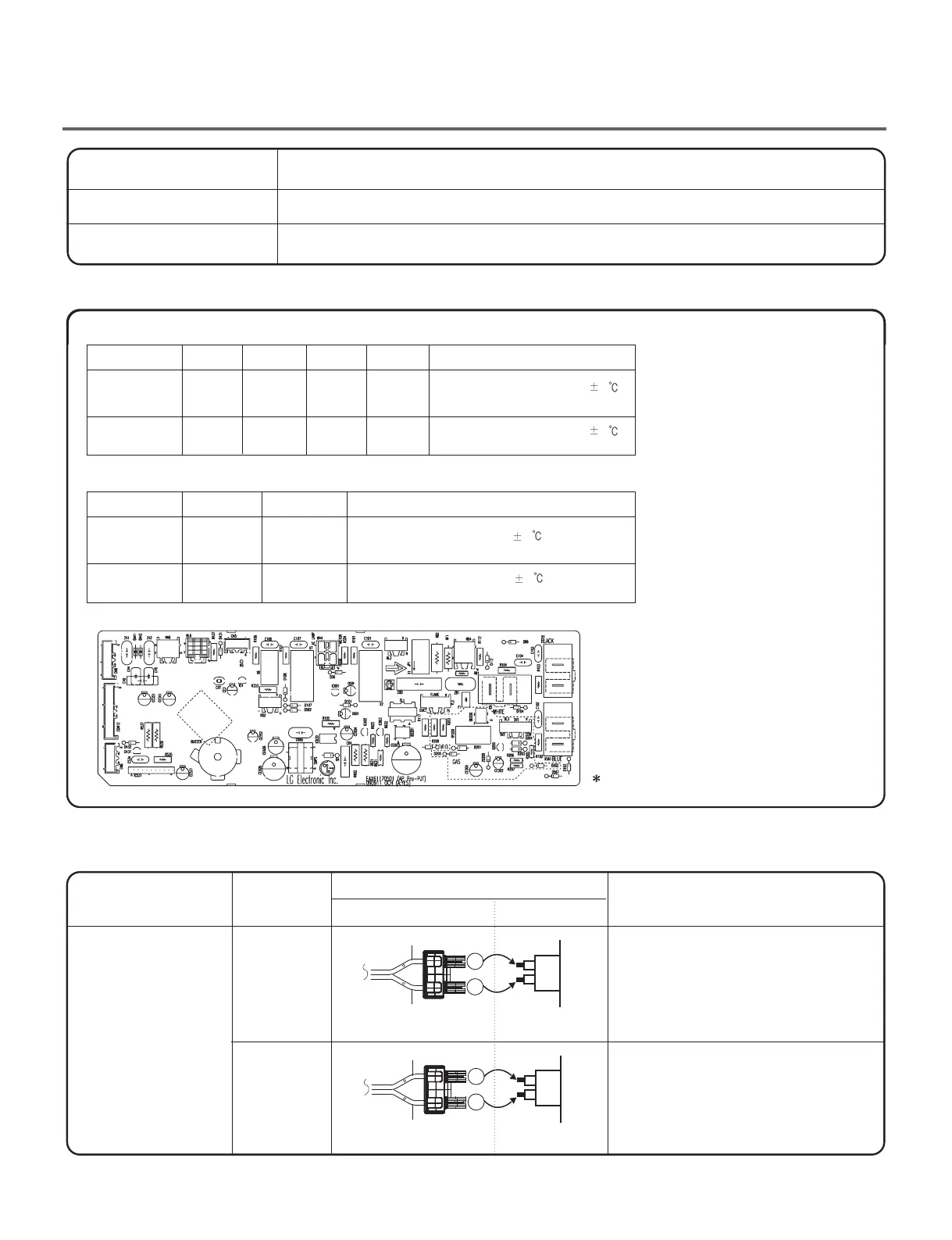
Connector Housing
Black
Yellow wire
Blue wire
Black wire
Black wire
Connector Housing Tap relay 1
Connector Housing Tap relay 2
Check the Matching color Between
Harness wire and tap relay.
(Black Housing – Black tap relay)
Check the Matching color Between
Harness wire and tap relay.
(White Housing – White tap relay)
White
Low
Extra Low
Low
Extra Low
on
on
on
on
on
O O
O O
on
off
off
Temperature Control below 68 4
Turn on Heater1 and Heater2.
Temperature Control below 52
4
Only Turn on Heater1.
Temperature Control below 70
4
Turn on Burner
PCB ASSEMBLY LAYOUT
Temperature Control below 47 4
Turn on Burner
< Table1 > : Connection of the tap relay with Heater (Electric)
< Table 2 > : Connection of the Tab Relay with Burner (Gas)
< Table1 > : Connection of tap relay with the tap relay of the PCB ASSEMBLY Electric
Color
Remark
Connection
Harness
PCB
Check the Tab Relays Connection properly.
Tab Relay 1
Tab Relay 2
Trans
 Loading...