SECTION 2. ELECTRICAL
ADJUSTMENTS
This set has been aligned at the factory and normally will not require further adjustment. As a result, it is not
recommended that any attempt is made to modificate any circuit. If any parts are replaced or if anyone tampers
with the adjustment, realignment may be necessary.
IMPORTANT
1. Check Power-source voltage.
2. Set the function switch to band being aligned.
3. Turn volume control to minimum unless otherwise noted.
4. Connect low side of signal source and output indicator to chassis ground unless otherwise specified.
5. Keep the signal input as low as possible to avoid AGC and AC action.
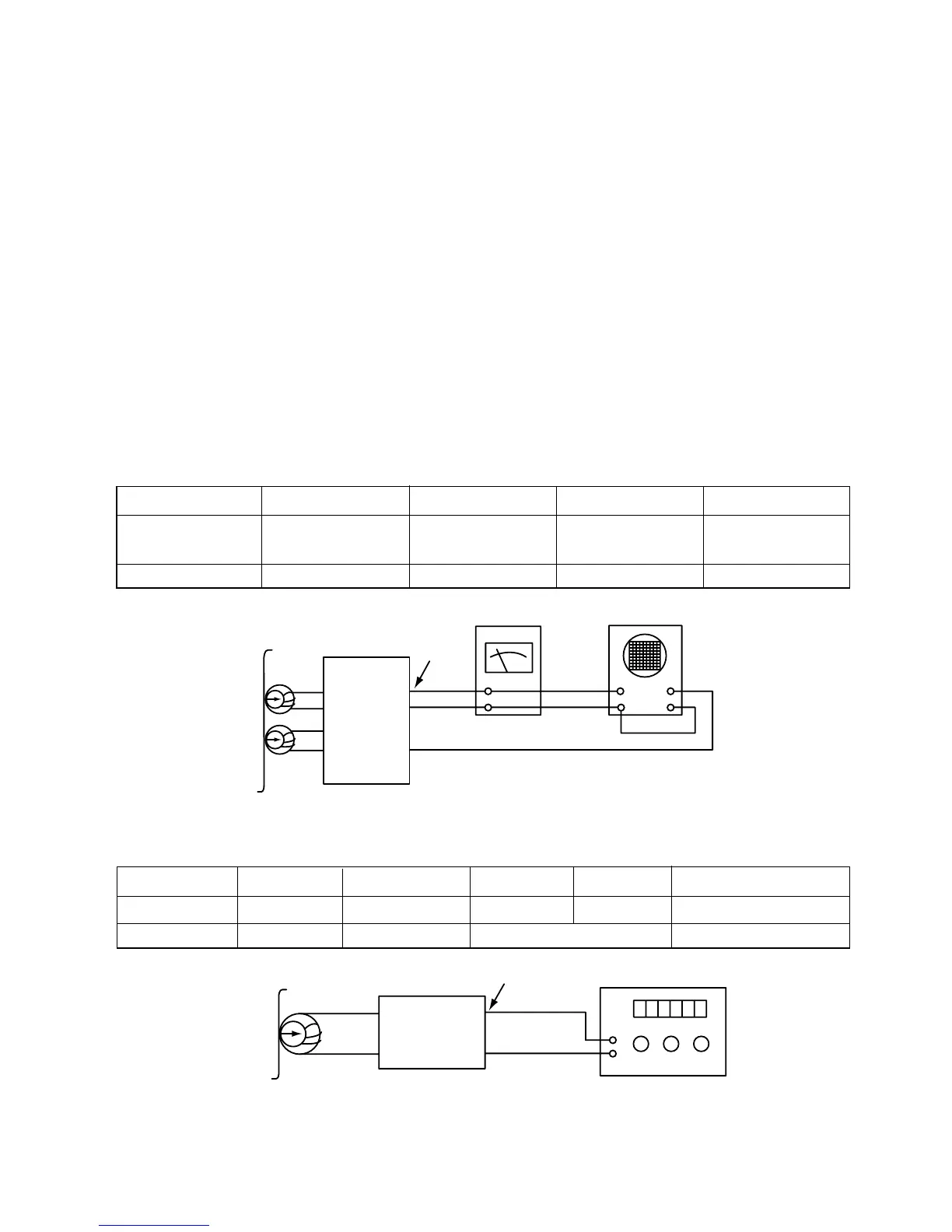
Deck Mode Test Tape Test Point Adjustment Adjust for
A Deck Playback MTT-114 Speaker Out
DECK Screw
Maximum
Azimuth Screw
B Deck Playback MTT-114 Speaker Out Azimuth Screw Maximum
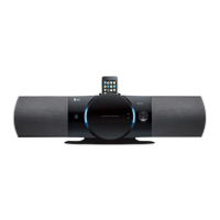
2. MOTOR SPEED ADJUSTMENT
Figure 2. Motor Speed Adjustment Connection Diagram
Deck Mode Test Tape Test Point Adjustment Adjust for Remark
Normal Speed MTT-111 Speaker Out VR201 3kHz ± 1% A Deck
HI-Speed MTT-111 Speaker Out more than 5.4kHz HI-Speed Dubbing Mode