Do you have a question about the LG FLATRON L1530S (L1530SM-AL**R) and is the answer not in the manual?
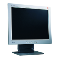
| Screen Size | 15 inches |
|---|---|
| Maximum Resolution | 1024 x 768 |
| Aspect Ratio | 4:3 |
| Brightness | 250 cd/m² |
| Input Signal | Analog |
| Input Connector | 15-pin D-Sub |
| Power Consumption (Typical) | 30 W |
| Weight | 3.5 kg |
| Display Type | LCD |
| Input Connectors | VGA |
Detailed specifications for the LCD panel, including size, pixel pitch, and color depth.
Information on viewing angles, luminance, and contrast ratio of the display.
Details on sync signals, video input, and operating frequencies for the monitor.
Specifications related to power input, voltage, and consumption of the monitor.
Conditions for operation, including temperature, humidity, and MTBF.
Physical dimensions of the monitor with tilt and base.
Specifies the net and gross weight of the monitor.
Warnings about replacing critical safety components and modifying original design.
Instructions for safely handling the LCD module, including mounting and ESD protection.
Cautionary advice for service operations, emphasizing tool usage to prevent shock.
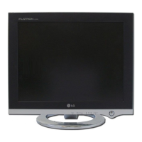
Description of the monitor's front control buttons and their functions.
Explanation of how to lock and unlock On-Screen Display settings.
Instructions for using the SET/AUTO button for automatic image adjustment.
Explanation of the video controller's role in signal amplification and conversion.
Details on the power part, including regulators and voltage conversion.
Description of the MICOM part, EEPROM, and its control functions.
Explanation of EMI components for compliance with marketing standards.
Describes the input rectifier and filter and output rectifier and filter functions.
Details on energy transfer via transformer and photo-coupler isolation.
Explains the function of signal collection for feedback to the primary.
Instructions for the Windows EDID V1.0 User Manual.
Steps for setting up the user port for EDID operations.
Guide on reading and writing EDID data, including editing manufacture information.
Steps to access the service OSD menu on the monitor.
Details on various service OSD menu items like Clear ETI, Auto Color, and NVRAM Init.
Diagram and information on connecting cables for testing and service.
Step-by-step troubleshooting flowchart for power-related issues.
Troubleshooting flowchart for 'No Raster' issues related to the LIPS board.
Troubleshooting flowchart for 'No Raster' issues with the MST9011B chip.
Flowchart for diagnosing and resolving issues related to DPM (Display Power Management).
Schematic diagram illustrating the H/V Sync detection circuit.
Schematic diagram detailing the amplifier and TMDS circuitry.
Schematic diagram for the video processor section of the monitor.
Schematic diagram showing output and input connectors and jacks.