EasyManua.ls Logo

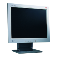
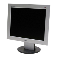
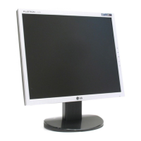
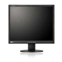
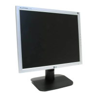
LG FLATRON L1550S-SN User Manual

LG FLATRON L1550S-SN
29 pages
To Next Page IconTo Next Page
Page #1 background imageLoading...
Page #1 background image
관리자
Model Description
MODEL
BRAND
Printing Specification
1. Trim Size (Format) : 215mm x 280 mm
2. Printing Colors
Cover : LG COLORS
Inside : Black
3. Stock (Paper)
Cover : Snow White 150 g/
Inside : Snow White 100 g/
4. Printing Method :
5. Bindery : Saddle stitch
6. Language : English
7. Number of pages : 28 (Including blank 1page)
Part No.
1.
2.
Service Guide Specification
Changes
4.
REV.
NO.
MM/DD/YY
SIGNATURE
CHANGE NO.
CHANGE CONTENTS
1
2
3
4
5
7
6
SUFFIX
LEE H.J
05.03.18
L1550S-SNN
L1550S-BNN
LG
3828TSL094N
KIM J.O
05.03.18
(1) Origin Notification
* LGEDI : Printed in Indonesia * LGEWA : Printed in U.K.
* LGESP : Printed in Brazil * LGEMX : Printed in Mexico
* LGENT : Printed in China * LGEIL : Printed in India
8
Special Instructions3.
Product Name
FLATRON L1550S-SN
FLATRON L1550S-BN
ANAUER
Question and Answer IconNeed help?

Do you have a question about the LG FLATRON L1550S-SN and is the answer not in the manual?

LG FLATRON L1550S-SN Specifications

General IconGeneral
Screen Size15 inches
Panel TypeTN
Resolution1024 x 768
Aspect Ratio4:3
Brightness250 cd/m²
Contrast Ratio500:1
Response Time16 ms
ConnectivityAnalog
Input SignalAnalog RGB
Weight3.5 kg
Input ConnectorD-Sub
Input ConnectorsVGA (D-Sub)

Summary

Model Description

Printing Specification

Special Instructions

Changes

LCD Characteristics

Optical Characteristics

Signal Specifications

Max Resolution

Power Supply Specifications

Environment Specifications

Dimensions

Weight

Precautions

Safety-Related Component Precautions

Essential critical parts should be replaced with manufacturer's specified parts.

LCD Module Handling Precautions

Handle the LCD module carefully to prevent damage to screen and electronic circuits.

Servicing Precautions

General Servicing Precautions

Precautions for safe servicing, including unplugging power and handling components.

Electrostatic Sensitive (ES) Devices

Techniques to prevent damage to ES devices from static electricity.

Soldering Guidelines

IC Removal and Replacement

Procedure for removing and replacing Integrated Circuits (ICs).

Discrete Transistor Replacement

Procedure for removing and replacing small-signal discrete transistors.

Power Transistor Replacement

Procedure for removing and replacing power output transistors.

Diode Removal and Replacement

Procedure for removing and replacing diodes.

Fuse and Resistor Replacement

Procedure for removing and replacing fuses and resistors.

Circuit Board Foil Repair

Repairing IC Connections

Procedure for repairing defective copper patterns at IC connections using jumper wires.

Repairing Other Connections

Procedure for repairing defective copper patterns at non-IC connections.

Timing Chart

Disassembly Procedure

Block Diagram

Block Diagram Description

Video Controller Part

Amplifies video signal, converts analog to digital, and interpolates resolution.

Power Part

Regulates power supply for LCD panel, scaler, and main board ICs.

MICOM Part

Stores control data, distinguishes sync signals, and controls modes.

LIPS Board Block Diagram

LIPS Operation Description

Describes the function of each component in the LIPS board block diagram.

Adjustment Procedures

Port Setup for EDID

Steps to set up the parallel port for EDID read/write operations.

EDID Read and Write

Procedure for reading and writing EDID data using WinEDID software.

Service OSD Menu

Auto Color Adjustment

Sets white balance, gain, and offset automatically.

NVRAM Initialization

Initializes the EEPROM (24C08).

Clear ETI

Initializes using time.

Aging Mode Selection

Selects Aging mode (on/off).

RGB 9300K Setting

Manually sets R/G/B values for 9300K color temperature.

RGB 6500K Setting

Manually sets R/G/B values for 6500K color temperature.

RGB Offset Setting

Manually sets R/G/B offset values (Analog Only).

RGB Gain Setting

Manually sets R/G/B gain values (Analog Only).

Module Selection

Selects the applied module.

Troubleshooting Guide

No Power Troubleshooting

Troubleshooting steps for when the monitor does not power on (indicator off).

No Raster (LIPS) Troubleshooting

Troubleshooting steps for no raster with LIPS power supply.

No Raster (Mstar) Troubleshooting

Troubleshooting steps for no raster with Mstar chipset.

DPM Troubleshooting

Troubleshooting steps for issues related to the Digital Panel Manager (DPM).

Wiring Diagram

Exploded View

Exploded View Parts List

Replacement Parts List

Schematic Diagrams

TSU56AL / TSU16AL Schematic

Schematic diagram for TSU56AL and TSU16AL components.

MICOM Schematic

Schematic diagram for the MICOM (Microcomputer) section.

Power Schematic

Schematic diagram for the power supply section.

Connector and Jacks Schematic

Schematic diagram for connectors and jacks.

Related product manuals