Do you have a question about the LG FLATRON L1919S and is the answer not in the manual?
Critical safety components must be replaced with manufacturer's parts to prevent hazards.
Handle LCD modules with care to prevent damage from ESD, heat, humidity, or liquids.
Follow safety procedures, unplug power, handle components with care, and use proper tools.
Minimize static discharge when handling sensitive electronic components to prevent damage.
Procedure for desoldering, removing, and soldering ICs on circuit boards.
Steps for removing and replacing transistors, including lead bending.
How to remove and replace power output transistors, including heat sink management.
Method for removing and replacing diodes, ensuring proper lead connection and polarity.
Steps for replacing fuses and resistors, maintaining component spacing.
Procedure for repairing foil traces at IC connections using jumper wires.
Method for repairing foil traces at non-IC connections using jumper wires.
In assembly state, rotate stand body to upper side.
Pull the stand and separate stand from monitor set.
Remove the screws.
Pull the front cover upward and separate latches.
Disassemble Connector.
In assembly state, rotate stand body to upper side.
Pull the stand and separate stand from monitor set.
Pull four latches each side the on stand body to outside.
Rotate the stand body to reverse of pulling direction.
Pull the stand body and separate the stand body from stand base.
Amplifies video signals, converts analog to digital, and outputs R, G, B signals.
Provides regulated power (3.3V, 1.8V) to main board, 12V to inverter, and 5V to panel.
Includes video controller, EEPROM for data, Reset IC, and Micom for sync distinction.
Contains EMI components to comply with global marketing EMI standards.
Transfers input AC voltage to DC voltage using a bridge rectifier and capacitor.
Transfers primary energy to secondary through a power transformer.
Stabilizes DC output by controlling duty cycle and monitoring over-power protection.
Provides feedback to the primary controller for stabilized DC output voltage.
Collects DC output changes and feeds back to the primary through a photo transistor.
Steps to copy UserPort.sys and run Userport.exe for port setup.
Procedures for running WinEDID.exe to read, write, and edit EDID information.
Describes features like Auto Color, NVRAM INIT, CLEAR ETI, AGING, R/G/B settings, and MODULE selection.
Troubleshooting steps for when the monitor has no power, including checking voltages and components.
Diagnoses issues where no raster or OSD is displayed on LIPS models.
Diagnoses issues where no raster or OSD is displayed on MSTAR models.
Troubleshooting steps for Display Power Management (DPM) issues.
Troubleshooting steps related to power supply issues, checking fuses, voltages, and components.
Troubleshooting steps for raster issues, including checking voltages and waveforms.
Detailed schematic of the scaler section, showing ICs, connections, and components.
Schematic diagram of the power supply and wafer sections.
Schematic diagram of the inverter circuit, showing components for lamp driving.
Detailed schematic of the power supply circuit, including SMPS components.
This document outlines the service procedures and technical information for the LG Flatron L1919S Color Monitor. It serves as a comprehensive guide for technicians, covering aspects from basic characteristics and operational details to troubleshooting, disassembly, and schematic diagrams. The manual emphasizes safety precautions throughout all servicing operations.
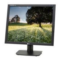
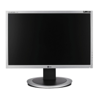
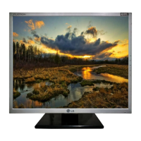
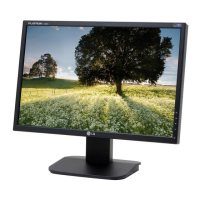
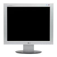
The LG Flatron L1919S is a color monitor designed for general use, featuring a TFT Color LCD Module. It supports a maximum resolution of 1280 x 1024 at 75Hz, making it suitable for a variety of computing tasks. The monitor's design incorporates a backlight unit with four CCFL lamps, providing illumination for the display. Power is supplied via an AC input ranging from 100V to 240V at 50/60Hz, with a typical power consumption of less than 33W during normal operation. The monitor also includes power-saving modes such as Stand-By, Suspend, and DPMS Off, which significantly reduce power consumption to less than 1W, indicated by an amber LED. When the power switch is off, the LED is also off, and power consumption is minimal.
The monitor's internal architecture includes a Video Controller Part, a Power Part, and a MICOM Part. The Video Controller Part is responsible for amplifying and converting analog video signals to digital, generating a pixel clock, and scaling the input to the native 1280 x 1024 resolution before outputting an 8-bit R, G, B signal to the transmitter. This part comprises a Scaler, ADC converter, TMDS receiver, and LVDS transmitter, supporting pixel clock ranges from 25MHz to 135MHz. The Power Part manages the power distribution within the monitor, converting the 5V input from the power board into 3.3V and 1.8V for various ICs on the main board. It also provides 12V for the inverter and 5V for the LCD panel. The inverter then converts the DC 12V to AC 700Vrms to power the backlight lamps. The MICOM Part integrates the video controller, an EEPROM IC for storing control data, and a Reset IC. The Micom identifies the polarity and frequency of H/V sync signals from the input cable and stores controlled data for different operating modes in the EEPROM.
The LIPS (LG Innotek Power Supply) board, detailed in the block diagram, handles the monitor's power supply functions. It includes EMI components to comply with global marketing standards, an input rectifier and filter to convert AC to DC voltage, an energy transfer section with a power transformer, and an output rectifier and filter for pulse width modulation control. The LIPS board also features a photo-coupler isolation mechanism to feed back DC output status to the primary controller, ensuring stabilized DC output voltage, and a signal collection function to monitor changes in DC output.
For user interaction and control, the monitor features an On-Screen Display (OSD) menu. In addition to the standard user OSD, a Service OSD menu is accessible for technicians. This service menu offers advanced adjustments such as Auto Color for W/B balance and automatic gain/offset settings, NVRAM INIT for EEPROM initialization, CLEAR ETI for time initialization, AGING mode control, and manual R/G/B gain and offset adjustments for 9300K and 6500K color temperatures. It also allows for module selection.
Maintenance and servicing of the LG Flatron L1919S monitor require adherence to strict safety precautions. Technicians are advised to be cautious of electric shock, especially when dealing with the inverter circuit, which can generate high voltages (around 650Vrms). It is crucial to disconnect the AC adapter before replacing backlight or inverter components. Special care must be taken when handling inverter circuit wires and connectors to prevent shorts and potential fire hazards. The manual also provides detailed guidelines for handling the LCD module with the backlight unit, emphasizing the importance of proper mounting, avoiding pressure or sharp objects on the panel, protecting against ESD, and ensuring the technician's body is grounded. The module should not be exposed to high temperatures, high humidity, or direct sunlight, and contact with water should be avoided. Cleaning the panel surface should be done with a soft material to prevent damage.
General servicing precautions include always unplugging the AC power cord before removing or reinstalling components, disconnecting electrical plugs, or connecting test substitutes. Testing high voltage should only be done with appropriate meters and probes, and discharging the picture tube anode must follow specific safety steps. Chemicals should not be sprayed on or near the receiver, and electrical contacts should be cleaned with a specified mixture of Acetone and isopropyl alcohol. It is important not to bypass any plug/socket B+ voltage interlocks and to ensure all solid-state device heat sinks are correctly installed before applying AC power. When using test receivers, the ground lead should always be connected first and removed last.
The manual also addresses the handling of Electrostatically Sensitive (ES) Devices, such as integrated circuits and field-effect transistors. Technicians are instructed to drain any electrostatic charge from their bodies by touching a known earth ground or wearing a discharging wrist strap before handling ES devices. Assemblies with ES devices should be placed on a conductive surface, and only grounded-tip soldering irons and anti-static solder removal devices should be used. Freon-propelled chemicals are to be avoided, and replacement ES devices should remain in their protective packaging until immediately before installation. Minimizing bodily motions when handling unpackaged ES devices is also recommended to prevent static electricity generation.
Detailed procedures for general soldering, "Small-Signal" Discrete Transistor removal/replacement, Power Output Transistor/Diode removal/replacement, IC removal/replacement, and Circuit Board Foil Repair are provided. These guidelines cover techniques for replacing components, repairing damaged copper patterns, and installing jumper wires, all while maintaining safety and preventing further damage to the device. The troubleshooting guide systematically addresses common issues such as "No Power," "No Raster (OSD is not displayed) – LIPS," "No Raster (OSD is not displayed) – MSTAR," and "Trouble in DPM," offering step-by-step diagnostic flows and waveform examples to assist in identifying and resolving problems.
| Screen Size | 19 inches |
|---|---|
| Resolution | 1280 x 1024 |
| Panel Type | TN |
| Brightness | 300 cd/m² |
| Contrast Ratio | 700:1 |
| Response Time | 5 ms |
| Display Type | LCD |
| Aspect Ratio | 5:4 |
| Viewing Angle | 160° (H) / 160° (V) |
| Connectivity | VGA |
| Input Connectors | D-Sub |