EasyManua.ls Logo

LG FLATRON L1940B - User Manual

LG FLATRON L1940B
34 pages
Print Icon
To Next Page IconTo Next Page
Loading...




Model Description
MODEL
BRAND
Printing Specification
1. Trim Size (Format) : 215mm x 280 mm
2. Printing Colors
Cover : LG COLORS
Inside : Black
3. Stock (Paper)
Cover : Snow White 150 g/
Inside : Snow White 100 g/
4. Printing Method :
5. Bindery : Saddle stitch
6. Language : English
7. Number of pages : 32( Including blank3pages)
Part No.
1.
2.
Service Guide Specification
Changes
4.
REV.
NO.
MM/DD/YY



CHANGE NO.
CHANGE CONTENTS
1
2
3
4
5
7
6
SUFFIX






L1740BN
L1940BN
LG
3828TSL096M






(1) Origin Notification
* LGEDI : Printed in Indonesia * LGEWA : Printed in U.K.
* LGESP : Printed in Brazil * LGEMX : Printed in Mexico
* LGENT : Printed in China * LGEIL : Printed in India
8
Special Instructions3.
Product Name
FLATRON L1740B
FLATRON L1940B
ANEUEP
ALEUEP
http://mycomp.su/x/ - Maintenance and Service Guide,Service Manual,Motherboard Schematics for Laptop/notebook, monitor
Ремонт мониторов. Запчасти и комплектующие для ноутбука. Схемы, сервис мануалы, инструкции по разборке ноутбука, мониторов
ВОССТАНОВЛЕНИЕ ДАННЫХ. г. Санкт-Петербург, Тел.(812)951-37-99, Тел.8-921-951-37-99, ICQ:573812745,service@it-lux.ru
Question and Answer IconNeed help?

Do you have a question about the LG FLATRON L1940B and is the answer not in the manual?

Overview

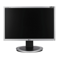
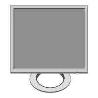
This document is a service manual for the LG FLATRON L1740B and L1940B color monitors, identified by chassis number CL-82 and part number 3828TSL096M. It provides detailed specifications, servicing precautions, troubleshooting guides, and diagrams for maintenance and repair.

Function Description:

The LG FLATRON L1740B and L1940B are TFT Color LCD monitors designed for displaying video signals. The monitors process analog video signals, convert them to digital, and scale them for display on the LCD panel. They support various resolutions and refresh rates, making them suitable for a range of computing environments. The internal architecture includes a video controller part, a power part, and a MICOM (Microcontroller) part, all working in conjunction to manage display functions, power supply, and control data.

Important Technical Specifications:

LCD Characteristics:

  • Type: TFT Color LCD Module
  • Active Display Area:
    • L1740B: 17 inch
    • L1940B: 19 inch
  • Pixel Pitch:
    • L1740B: 0.264 (H) x 0.264 (V)
    • L1940B: 0.294 (H) x 0.294 (V)
  • Size (Dimensions):
    • L1740B: 358.5 (H) x 296.5 (V) x 17.0 (D)
    • L1940B: 404.2 (H) x 330.0 (V) x 20.0 (D)
  • Color Depth:
    • L1740B: 8bit, 16.2M colors
    • L1940B: 16.7M colors
  • Electrical Interface: LVDS
  • Surface Treatment: Hard-coating (3H), Anti-Glare
  • Operating Mode: Normally White, Transmissive
  • Backlight Unit: Top/Bottom edge side 4-CCFL (Cold Cathode Fluorescent Lamp)

Optical Characteristics:

  • Viewing Angle by Contrast Ratio ≥ 10:
    • L1740B: Left: -60° min., -70°(Typ); Right: +60° min., +70°(Typ); Top: +45° min., +60°(Typ); Bottom: -50°min., -60°(Typ)
    • L1940B: Left: -85° min., -88°(Typ); Right: +85° min., +88°(Typ); Top: +85° min., +88°(Typ); Bottom: -85° min., -88°(Typ)
  • Luminance: 200(min), 250(Typ)
  • Contrast Ratio:
    • L1740B: 300(min), 450(Typ)
    • L1940B: 350(min), 500(Typ)

Signal (Refer to the Timing Chart):

  • Sync Signal Type: Separate Sync, SOG (Sync On Green), Composite Sync
  • Video Input Signal:
    • Type: R, G, B Analog
    • Voltage Level: 0~0.71 V
    • Input Impedance: 75 Ω
  • Operating Frequency:
    • Horizontal: 30~83kHz
    • Vertical: 56~75Hz

Max. Resolution:

  • Analog: 1280 x 1024 / 75Hz

Power Supply:

  • Power: AC 100-240V~, 50/60Hz, 1.0A
  • Power Consumption:
    • L1740B: less than 43 W (Normal), less than 1 W (Stand-by/Suspend/DPMS Off)
    • L1940B: less than 45 W (Normal), less than 1 W (Stand-by/Suspend/DPMS Off)
    • LED Color: Blue (Normal), Amber (Stand-by/Suspend/DPMS Off)

Environment:

  • Operating Temperature: 10°C~35°C (50°F~95°F) (Ambient)
  • Relative Humidity: 10%~80% (Non-condensing)
  • MTBF: 50,000 HRS with 90% Confidence level
  • Lamp Life:
    • L1740B: 50,000 Hours (Min)
    • L1940B: 40,000 Hours (Min)

Dimensions (with TILT/SWIVEL):

  • L1740B:
    • Width: 394 mm (15.51")
    • Depth: 221.8 mm (8.73")
    • Height: 396 mm (15.59")
  • L1940B:
    • Width: 442.6 mm (17.43")
    • Depth: 240 mm (9.45")
    • Height: 434.9 mm (17.12")

Weight (with TILT/SWIVEL):

  • L1740B:
    • Net. Weight: 5.3 kg (11.69 lbs)
    • Gross Weight: 7.4 kg (16.32 lbs)
  • L1940B:
    • Net. Weight: 6.8 kg (14.99 lbs)
    • Gross Weight: 9.3 kg (20.51 lbs)

Usage Features:

The monitors are designed for ease of use with standard analog video input. The service manual details the internal components and their interactions, which are crucial for understanding how the monitor functions. The MICOM part stores control data and manages the display modes based on the H/V sync signals from the input cable. The power part ensures stable power delivery to all components, regulating voltages as needed.

Maintenance Features:

Servicing Precautions:

The manual emphasizes safety precautions, including always unplugging the AC power cord before servicing, testing high voltage with appropriate meters, and safely discharging the picture tube anode. It also warns against spraying chemicals on the receiver and highlights the importance of using specified test fixtures.

Electrostatically Sensitive (ES) Devices:

Special care is required when handling ES devices (semiconductors, integrated circuits, field-effect transistors, chip components) to prevent damage from static electricity. Technicians are advised to drain electrostatic charge from their bodies, place ES devices on conductive surfaces, use grounded soldering irons and anti-static solder removal devices, avoid freon-propelled chemicals, and keep replacement ES devices in protective packaging until installation.

General Servicing Precautions:

  • Unplug the AC power cord before removing/reinstalling components, disconnecting/reconnecting electrical plugs, or connecting test substitutes.
  • Discharge the picture tube anode safely.
  • Do not spray chemicals on the receiver.
  • Clean electrical contacts with a specific mixture of Acetone and Isopropyl Alcohol.
  • Do not defeat B+ voltage interlocks.
  • Ensure all solid-state device heat sinks are correctly installed before applying AC power.
  • Always connect the test receiver ground lead first and remove it last.

Circuit Board Foil Repair:

Guidelines are provided for repairing damaged copper foil on printed circuit boards, emphasizing careful removal of damaged foil, scratching away solder resist, and using jumper wires for connections, especially for IC pins and other connections. Insulated jumper wires should be carefully dressed to avoid contact with other components.

Service OSD (On-Screen Display):

The service OSD menu provides advanced calibration and diagnostic options:

  1. Turn off the power switch.
  2. Wait 5 seconds, then press MENU and POWER switches with a 1-second interval.
  3. The SVC OSD menu includes:
    • Auto Color: For W/B balance and automatic gain/offset adjustment.
    • NVRAM INIT: EEPROM initialization (24C08).
    • CLEAR ETI: To initialize using time.
    • AGING: Select Aging mode (on/off).
    • R/G/B-9300K / R/G/B-6500K: Manual adjustment of R/G/B values for specific color temperatures.
    • R/G/B-Offset / R/G/B-Gain: Manual adjustment of R/G/B offset and gain values (Analog Only).
    • MODULE: To select the applied module.

Troubleshooting Guide:

The manual includes flowcharts for diagnosing common issues such as "No Power," "No Raster (OSD is not displayed) – LIPS," "No Raster (OSD is not displayed) – MSTAR," and "Trouble in DPM." These guides direct technicians through a series of checks, including voltage measurements, pulse checks, and component verifications, to identify the root cause of a problem. Waveforms for specific test points are provided to aid in diagnosis.

Exploded View and Parts List:

Detailed diagrams and lists of all components, including part numbers and descriptions, are provided for easy identification and replacement. This includes cabinet assemblies, LCD panels, back covers, tilt swivel assemblies, power boards (PWBs), main total assemblies, metal frames, shields, control knobs, and front LED lenses.

Wiring Diagram:

A comprehensive wiring diagram illustrates the connections between different modules within the monitor, including connector assembly part numbers, which is essential for proper reassembly and troubleshooting.

Block Diagrams:

Separate block diagrams are provided for the L1740B and L1940B models, illustrating the functional relationships between the LCD module, video controller (FE2040), MICOM (MTV412), power supply (LIPS), and D-SUB input. These diagrams show the signal flow and power distribution within the monitor.

Description of Block Diagram:

  • Video Controller Part (FE2040): Amplifies video signals, converts analog to digital using a pixel clock (25MHz to 135MHz), scales input to 1280x1024 resolution, and outputs 8-bit R, G, B signals.
  • Power Part: Consists of a 3.3V regulator (from 5V), 12V for the LCD panel, 5V for MICOM, and further conversions to 3.3V and 1.8V for scaler and KTA1273.
  • MICOM Part (MTV412): Contains an EEPROM IC for control data storage and distinguishes H/V sync polarity and frequency from the signal cable.

This manual is a critical resource for anyone involved in the maintenance and repair of the LG FLATRON L1740B and L1940B monitors, ensuring proper diagnosis, repair, and safety procedures are followed.

LG FLATRON L1940B Specifications

General IconGeneral
BrandLG
ModelFLATRON L1940B
CategoryMonitor
LanguageEnglish

Related product manuals