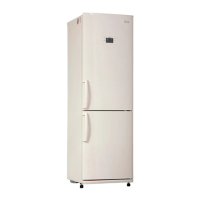
Do you have a question about the LG GA-B409U*QA and is the answer not in the manual?
| Brand | LG |
|---|---|
| Model | GA-B409U*QA |
| Category | Refrigerator |
| Language | English |
Details on the characteristics and properties of R600a refrigerant used in the appliance.
Specifications for the location where the refrigerator should be installed for safe and optimal operation.
Essential checks and confirmations required before commencing any servicing procedures.
Procedure for safely recharging air into the compressor system during servicing.
Important safety and handling precautions to follow before reversing the refrigerator door.
Step-by-step instructions on how to reverse the opening direction of the refrigerator door.
Instructions for safely removing the refrigerator and freezer doors from the unit.
Steps to remove and access the door switch mechanism for inspection or replacement.
Procedure for removing the internal refrigerator lamp assembly.
Instructions for carefully disassembling the display control unit.
Guide to removing the cooling fan and its motor assembly.
Steps for removing the defrost control system components.
Instructions for disassembling the air damper control mechanism.
Procedure for removing the defrosting heater sheath.
Information on compressor role, composition, usage notes, and handling precautions.
Details on the PTC starter's composition, role, and proper usage guidelines.
Schematic diagram illustrating the circuit for the PTC starter and motor.
Diagnostic steps for issues related to the compressor and other electrical components.
Diagnostic procedures for the relay assembly, including PTC and OLP components.
Troubleshooting guide for other electrical parts not covered in previous sections.
Methods and steps for detecting refrigerant leaks within the refrigeration cycle.
Overview of the appliance's functions and user interface controls.
Explanation of how to select and adjust temperature settings for different compartments.
Details on the super freezing feature for rapid cooling.
Explanation of the vacation mode and its operational parameters.
Information regarding the buzzer sound activated by button presses.
Description of the automatic defrosting cycle and its triggers.
Sequence of operation for electrical components to prevent noise and damage.
Guidance on using the self-test feature for diagnosing appliance issues.
Detailed instructions for performing function tests on the refrigerator's systems.
Description and voltage specifications for the main electric circuits.
Explanation of the oscillation circuit's role in timing and communication.
Details on the reset circuit functionality for the MICOM.
Procedure for checking the operation of loads and the buzzer.
Method to verify the detection of door opening and closing.
Description of the temperature sensor circuits and their readings.
Explanation of the circuit for inputting test switch signals.
Table and explanation for adjusting temperature compensation values.
Diagram showing the layout and components of the main PCB.
List of replaceable parts for the main PCB assembly.