Do you have a question about the LG GN-M492Y*Y and is the answer not in the manual?
Procedure for recharging the compressor with refrigerant, including vacuum operation and gas addition.
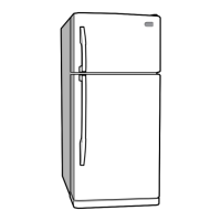
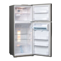
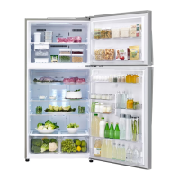
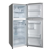
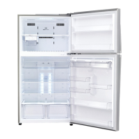
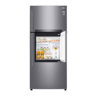
Illustrates the parts and features of the refrigerator compartments.
Instructions for disassembling the freezer and refrigerator doors.
Procedure for removing the door switch.
Steps to remove the fan and fan motor assembly.
Procedures for removing the Defrost Control Assembly and Control Box-R.
Instructions for removing freezer and refrigerator lamps.
Explanation of the compressor's role, composition, and usage notes.
Details on PTC-Starter composition, role, and operating principles.
Defines and explains the role of the Over Load Protector.
Electrical schematic for specific refrigerator models.
Electrical schematic for specific refrigerator models.
Troubleshooting guide for compressor and related electric components.
Troubleshooting steps for PTC and Over Load Protector issues.
Troubleshooting for other electrical components affecting cooling.
A chart listing complaints, points to check, and remedies.
Troubleshooting chart for refrigerating cycle issues like leakage and clogs.
Explains the basic functions of the MICOM control system.
Details the operation and features of the Super Cool function.
Describes how the freezer fan speed is controlled.
Explains the open door alarm function and its timing.
Describes the buzzer sound behavior.
Explains the defrosting cycle timing and conditions.
Outlines the sequential start-up of components during operation and testing.
Explains the error codes and their display for specific models.
Instructions for operating and using the test modes.
Explains the power circuit of the PCB.
Describes the oscillation and reset circuits for the MICOM.
Details circuits for load drive and open door detection.
Describes the temperature sensor circuits and their states.
Input and compensation circuits for the refrigerator.
Circuit for key input and display light control.
Table of resistance values for freezer and refrigerator sensors.
Troubleshooting specific to PCB components and functions.
Diagram and parts list for the Main PCB Assembly.
Parts list for the display PCB assembly.
Schematic diagram of the Printed Wiring Board (PWB).
| Refrigerant | R600a |
|---|---|
| Bio Shield (Gasket) | Yes |
| Water Dispenser | No |
| Adjustable Shelves | Yes |
| Defrost Type | Automatic |
| Height | 1720 mm |
| Width | 70.5 cm |
| Model | LG GN-M492Y*Y |