The following description is basically for GN-M492Y*Y/ GN-M492Y*Q/ GN-M492Y*C/ GN-B492Y*Q / GN-B492Y*C
For the other models, refer to the diagram of the entire PCB circuit.
7-1 FUNCTION
7-1-1 FUNCTION
1. When the appliance is plugged in, it is set to ‘Medium’. Each time the button is pushed, Exterior display is set to
‘3’→’2’→’1’→’0’→’6’→’5’ →’4’ in order and Interior display is set to ‘R2’→’R3’→’R4’→’R0’→’R1’ .
2. When the power is initially applied or restored after a power failure, it is automatically set to ‘3’ against the interruption of
electric power.
7. DESCRIPTION OF FUNCTION & CIRCUIT OF MICOM
- 18 -
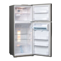
u GN-M492Y*Y
GN-M492Y*Q
GN-B492Y*Q
MIN MAX
REF. TEMP. CONTROL
R0 R1 R2 R3 R4
Temp
Medium
/
Medium
/
Control
Low
Low
Medium
High
High
TEMP(˚C)
ROOM REFRIGERATOR
Temp Very
Medium
/
Medium
Medium
/ Very
Control Low
Low
Low High
High
High
TEMP(˚C) 6 5 4 3 2 1 0
ROOM REFRIGERATOR
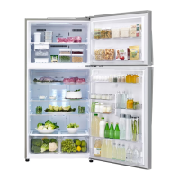
u GN-M492Y*C
GN-B492Y*C
 Loading...