Do you have a question about the LG GoldStar FMH-49A and is the answer not in the manual?
Warning and guidelines for safe handling of laser equipment.
Technical details for the audio amplifier output and distortion.
Performance parameters for FM, MW, and LW tuning.
Technical data for the tape deck's speed, wow/flutter, and frequency response.
Performance metrics for the Compact Disc Player section.
Technical data for the optional record player functionality.
Overall power, consumption, and physical dimensions of the unit.
Key considerations before performing any adjustments on the unit.
Identifies specific points on the main circuit board for testing and adjustment.
Identifies specific points on the CD circuit board for testing and adjustment.
Procedure for FM IF alignment using a DC voltmeter.
Procedure for FM IF alignment using a signal generator and distortion meter.
Method for adjusting stereo separation in the FM multiplex section.
Steps to adjust the FM stereo beacon sensitivity level.
Procedure to align the tape head azimuth for optimal playback.
Method for setting the correct motor speed for tape playback.
Lists necessary equipment for CD player adjustments.
Details the circuit diagram for the focus and tracking gain adjustment jig.
Pre-adjustment settings for various potentiometers.
Procedure to adjust the Phase Locked Loop Voltage Controlled Oscillator.
Method for adjusting the E-F balance in the CD player.
Steps for setting focus offset using an oscilloscope.
Procedure for focus offset adjustment using a jitter meter.
Adjusting focus gain with the aid of a specialized jig.
Method for focus gain adjustment without using a jig.
Procedure for adjusting tracking gain using a jig.
Confirms focus offset levels after adjustment.
Explains the RF amplifier's role in processing optical pickup signals.
Describes the function of the focus error amplifier circuit.
Details the operation of the tracking error amplifier.
Explains the mirror circuit's function for peak and bottom hold.
Describes the circuit that generates a timing window for focus servo lock.
Explains how the EFM comparator converts RF signals to binary values.
Details the circuit that detects disc defects using time constants.
Explains the block diagram and operation of the focus servo system.
Details the block diagram and operation of the tracking servo system.
Explains the spindle servo and low-pass filter operation.
Describes the VCO loop filter and the 8.64MHz VCO circuit.
Displays the HF signal waveform during normal playback.
Shows the EFM signal waveform during normal playback.
Illustrates focus coil drive waveforms during focus search failure.
Displays tracking coil drive waveforms during traverse.
Overview of the CD player's functional blocks and interconnections.
Detailed circuit diagram for the main operational components.
Circuit diagram for the front panel and control interface.
Circuit diagram specific to the tape deck mechanism.
Circuit diagram for the Compact Disc Player components.
Physical layout of components on the main printed circuit board.
Physical layout of components on the front and volume control P.C. board.
Physical layout of components on the CD player's printed circuit board.
Physical layout of components for the audio section's printed circuit board.
Internal structure and pinout of the BA6209 IC.
Internal structure and pinout of the CXA1081S IC.
Internal structure and pinout of the CXA1082 IC.
Internal structure and pinout of the KA9256 IC.
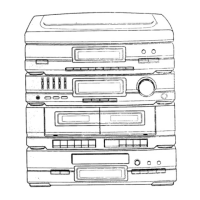
Breakdown of the unit's external casing and associated parts.
Diagram showing the assembly of the tape deck mechanism.
Detailed parts list for the tape deck mechanism.
Breakdown of the CD player mechanism and its components.
Exploded view and parts list for the optional record player.
List of replaceable parts for the unit's cabinet.
List of replaceable parts for the tape deck mechanism.
List of replaceable parts for the CD mechanism.
List of all capacitors with their specifications and part numbers.
| Brand | LG |
|---|---|
| Model | GoldStar FMH-49A |
| Category | Stereo System |
| Language | English |