Do you have a question about the LG GR-J303UG Series and is the answer not in the manual?
Detailed specifications for the GR-J303UG model, including capacity, dimensions, and cooling system.
Details on various functions including display, storage, seasoning, flavor keeping, and temperature control.
Explanation of the power supply circuit, including rectification, switching, and feedback components.
Details on the oscillation circuit for synchronization and clock generation within the MICOM.
Explanation of the reset circuit for initializing the MICOM upon power application or failure.
Circuit diagrams for driving loads like fans, heaters, and the buzzer mechanism.
Input circuits for detecting test switch signals and the reed switch for the single motor damper.
Details on upper, middle, lower, defrost, and ambient temperature sensors and their resistance characteristics.
Circuit for driving the single motor damper and detecting its open/close status via a reed switch.
Circuit for driving the middle compartment stepping motor damper, including control signals.
Circuit for driving the 3-way valve stepping motor for compartment switching.
Circuits for temperature compensation and cut-off compensation for cold/warm conditions.
Circuitry for information exchange between the main MICOM and the display PCB MICOM.
Diagram and list of components for the main Printed Circuit Board (PCB).
Diagram and list of components for the display Printed Circuit Board (PCB).
Circuit diagram for the main Printed Circuit Board (PCB) assembly, LED module type.
Circuit diagram for the display Printed Circuit Board (PCB) assembly.
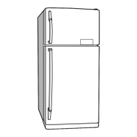
Exploded view illustration of the refrigerator components for service identification.
| Energy Star Certified | Yes |
|---|---|
| Ice Maker | Yes |
| Water Dispenser | Yes |
| Smart Diagnosis | Yes |
| Noise Level | 39 dB |
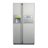
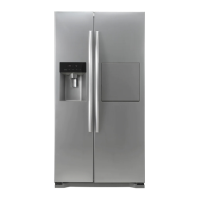
| Color | Stainless Steel |