Do you have a question about the LG GR-S462 and is the answer not in the manual?
Procedure for refilling the refrigeration system with refrigerant.
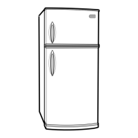
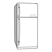
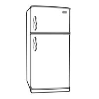
Instructions for removing refrigerator doors.
Procedure to remove and disconnect the door switch.
Steps for removing the thermistor and associated components.
Guide to disassembling the fan and fan motor assembly.
Steps to remove the defrost control assembly.
Instructions for lamp removal and replacement.
Procedure for accessing and removing the control box.
Explanation of compressor function, composition, and usage notes.
Details about the PTC starter's composition, role, and operation.
Definition, role, and handling precautions for the OLP.
Troubleshooting steps for compressor and related electrical parts.
Diagnostic procedures for PTC starters and Over Load Protectors.
Troubleshooting guide for miscellaneous electrical components.
A systematic chart for diagnosing common appliance complaints.
Troubleshooting guide for problems with the refrigerating cycle.
Explains temperature control settings and operational sequences.
Details error codes and their interpretation for diagnostics.
Overview of the Printed Circuit Board (PCB) functions and circuits.
Resistance values for temperature sensors at various temperatures.
General troubleshooting steps for common cooling and defrosting issues.
Diagram showing the layout of components on the main PCB.
Comprehensive list of replaceable parts with specifications.
| Brand | LG |
|---|---|
| Model | GR-S462 |
| Category | Refrigerator |
| Language | English |