Do you have a question about the LG GR-S552 and is the answer not in the manual?
Details the process of recharging refrigerant in the compressor.
Technical specifications for the GR-S552 model.
Technical specifications for the GR-S592 model.
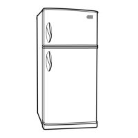
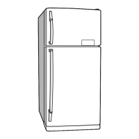
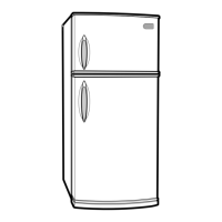
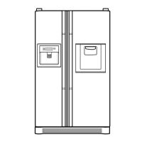
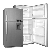
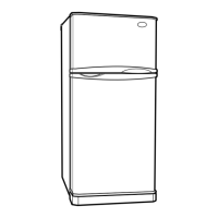
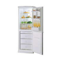
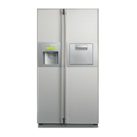
Visual identification of refrigerator components.
Procedures for disassembling freezer and refrigerator doors.
Steps to remove and disconnect the door switch.
Instructions for disassembling the fan and fan motor assembly.
Procedure for removing the defrost control assembly.
Steps for replacing freezer and refrigerator lamps.
Method for removing the control box.
Role, composition, and usage notes for the compressor.
Details on the PTC starter's composition, role, and usage.
Definition and role of the Over Load Protector.
Troubleshooting flowchart for compressor and related electric parts.
Troubleshooting steps for PTC and OLP components.
Troubleshooting for other electrical components affecting cooling.
Chart correlating complaints with checks and remedies.
Troubleshooting and diagnosis of refrigerating cycle problems.
Overview of temperature control, freezer/refrigerator fan operations, and defrosting cycles.
Sequential component startup, defrosting error codes, and diagnostic modes.
Description and voltage details of the power circuit.
Function of oscillation and reset circuits for MICOM operation.
Circuits for load drive, temperature sensors, and door detection.
Circuits for temperature compensation, key input, and display lights.
Resistance values for sensors at various temperatures.
Diagnosis and solutions for common operational issues.
Diagram of the Main Printed Circuit Board assembly.
List of replaceable parts with part numbers and specifications.
Diagram and parts list for the display PWB.
| Brand | LG |
|---|---|
| Model | GR-S552 |
| Category | Refrigerator |
| Language | English |