Do you have a question about the LG LFC24770ST and is the answer not in the manual?
Step-by-step guide for door removal and replacement.
Procedure for aligning refrigerator doors to ensure proper spacing.
Instructions for removing and replacing the evaporator fan motor.
Steps for replacing the defrost control assembly and its components.
Procedures for replacing interior compartment lamps.
Guide for removing and disconnecting the multi duct assembly.
Steps for removing and replacing the main Printed Circuit Board.
Detailed instructions for the removal and reinstallation of the pullout drawer.
Details on compressor role, usage, and cover removal.
Explanation of the protection logic for compressor and related components.
Visual identification of the main PCB for different models.
Visual identification of the display and sub PCBs.
Diagnosing freezer sensor errors using resistance charts.
Diagnosing refrigerator sensor errors using resistance charts.
Diagnosing icing sensor errors using resistance charts.
Diagnosing defrost sensor errors using resistance charts.
Diagnosing defrost heater errors, checking resistance and voltage.
Diagnosing freezer fan errors, checking motor and voltage.
Diagnosing condenser fan errors, checking motor and voltage.
Diagnosing communication errors by checking voltages.
Troubleshooting steps for a malfunctioning freezer LED lamp.
Troubleshooting steps for a malfunctioning refrigerator LED lamp.
Diagnosing and resolving poor cooling in the fresh food compartment.
Diagnosing and resolving poor cooling in the freezer compartment.
Guide to entering test modes and removing Terminal Position Assurance.
Temperature vs. resistance and voltage chart for FRZ/icing sensors.
Temperature vs. resistance and voltage chart for REF/defrost sensors.
Procedure for checking fan errors and understanding motor lock status.
Information on testing defrost controller fuse-M and sensor.
Procedure for testing the sheath heater resistance.
Testing procedure for the damper, including wirering and resistance.
Testing procedure for refrigerator and freezer door switches.
Simplified check of the PCB for compressor issues.
Overview of test modes for compressor diagnosis.
Flowchart for diagnosing compressor issues via LED blink codes.
Checking IPM output voltage to ensure compressor is receiving power.
Diagnosing compressor faults based on LED blink patterns.
Checking harness, capacitor specifications, and compressor terminals.
Checking protection logic and performing sealed system diagnosis.
Chart for diagnosing refrigeration cycle issues based on cause.
Flowchart for diagnosing sealed system problems causing "Not Cooling".
Explanation of the ice maker and dispenser's operational sequence.
Details on icemaker start, icemaking, and ice ejection modes.
Procedure for testing the icemaker's functions.
Explanation of water supply function and the water supply time table.
Basic functions including temperature control and mode changes.
Instructions to switch between Fahrenheit and Celsius display modes.
Explanation of the ICE PLUS function for enhanced cooling.
Overview of automatic diagnosis and error code display on the panel.
Guide to operating and exiting test modes for product inspection.
Exploded diagram showing the overall case parts of the refrigerator.
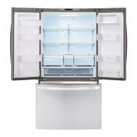
Exploded view of the freezer compartment components.
Exploded view of the refrigerator compartment components.
Exploded view of refrigerator and freezer door components.
Exploded view of the ice maker assembly components.
| Brand | LG |
|---|---|
| Model | LFC24770ST |
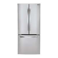
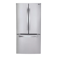
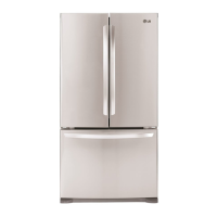
| Type | French Door Refrigerator |
| Total Capacity | 23.7 cu. ft. |
| Ice Maker | Yes |
| Water Dispenser | Yes |
| Door Finish | Stainless Steel |
| Energy Star Certified | Yes |
| Width | 32 3/4 inches |